
Detector And Controller

The circuit employs a 555 timer integrated circuit configured as a Schmitt trigger to effectively sense analog signals while controlling digital outputs. The unique arrangement of the 555 timer allows for the combination of hysteresis and signal conditioning, enhancing the circuit's stability and performance.
In this setup, the trigger and threshold pins of the 555 timer are connected, creating a feedback loop that enables the internal comparators to control the state of the flip-flop. This configuration is particularly advantageous as it minimizes component count while maintaining functionality. The inclusion of hysteresis is critical, as it prevents the circuit from oscillating due to noise or rapid fluctuations in the input signal, thereby ensuring reliable operation.
The operational amplifier (op amp) designated as U2 is employed to establish the trip points for the circuit. This op amp allows for precise adjustment of the threshold levels, which can be fine-tuned to define the on and off states of the output signal. By adjusting the feedback resistors associated with U2, the amount of hysteresis can be controlled, allowing for tailored performance based on the specific application requirements.
This circuit configuration is particularly suited for applications such as a Nicad battery-charge controller, where it is essential to monitor the battery voltage and switch the charging state accordingly. The 555 timer's ability to handle varying input conditions while providing a clean, stable output makes it an ideal choice for this type of application. Furthermore, the reduced component count not only simplifies the design but also enhances reliability and ease of implementation. Many applications require analog signals to be sensed and digital signals to be controlled. A way to detect these p oints is by using a 555 timer in an unconventional configuration. This method will also add hysteresis to the circuit and guard against oscillation. The 555 supplies two comparators and a flip-flop eliminates the oscillation. Using this classic timer in the new configuration also reduces the component count. The circuit shows the 555"s trigger and threshold pins tied together. This enables the comparators to set and reset the flip-flop. Op amp U2 supplies both the trip-point setting and a way to adjust the hysteresis for on and off points. One application where this circuit would be useful is in a Nicad battery-charge controller.
Related Circuits
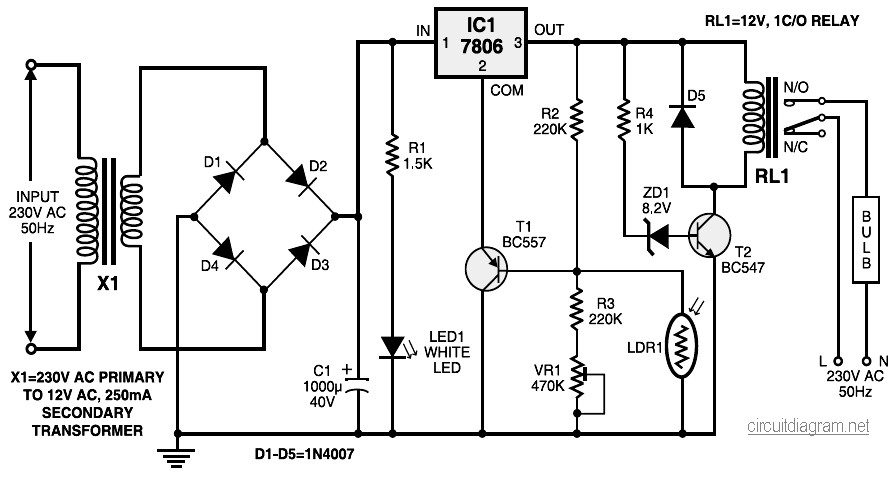
During nighttime, when no light falls on LDR1, it offers a high resistance at the base junction of transistor T1. Consequently, the bias is significantly reduced, and T1 does not conduct. This effectively removes the common terminal of IC1...
This circuit responds to the presence of any conductive object, including humans. It does not detect object movement but can function as a proximity sensor. The circuit operates on the principle of capacitive sensing, utilizing a capacitor to detect changes...
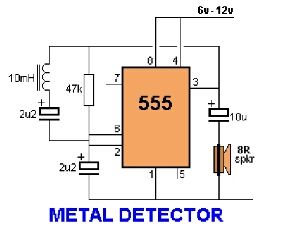
Assemble the circuit on a perfboard or PCB, excluding the inductor. Attach two long wires in place of the inductor. Use a long rod and position the inductor. The circuit assembly begins with the preparation of a perfboard or printed circuit...
The motion detector circuit consists of two components: the emitter and the sensor/detector. The emitter is constructed using an infrared emitting diode that is reverse-biased to a 5-volt source. The sensor employs the MRD821 to detect the infrared beam...
The following circuit illustrates a stepper motor controller. This circuit is based on the PIC16F84A integrated circuit. Features: a transistor is utilized to drive the motor. The stepper motor controller circuit employs the PIC16F84A microcontroller, which serves as the central...
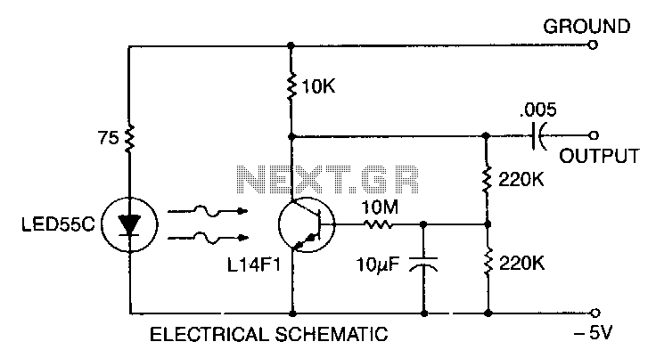
This self-biasing configuration is useful whenever small changes in light level must be detected, such as when monitoring very low flow rates by counting drops of fluid. In this bias method, the photodarlington is bias stabilized by feedback from...