
CUSTOMIZE YOUR DOORBELL
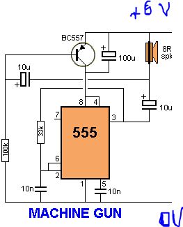
The integrated circuit (IC) in question is designed for a specific application, such as a doorbell system that produces a unique sound. The IC's pin configuration is vital for understanding its functionality and ensuring proper connections in the circuit design. The GND pin serves as the reference point for the entire circuit, providing a stable low voltage level. The TRIG pin is responsible for initiating the sound output; when activated, it sends a signal to the internal circuitry to produce the desired sound effect.
The RESET pin is a critical component for managing the timing sequence of the sound output. By connecting this pin to ground, the user can reset the timing interval, allowing for the sound to be replayed. However, it is important to note that the timing will not restart until the voltage on the RESET pin exceeds approximately 0.7 volts. This feature is particularly useful in applications where precise timing control is necessary, such as in sound effects that require specific intervals between activations.
In addition to the electronic components, the presentation of the project is also important. Clear and concise instructions, supplemented by well-labeled diagrams, can significantly enhance the understanding of the circuit for individuals with varying levels of expertise. Visual aids should be clear and focused, with attention to detail to ensure that all components and connections are easily identifiable. Utilizing photo-editing software can help achieve a professional appearance for the project documentation.
In conclusion, a well-structured approach to both the electronic design and its presentation will facilitate a better understanding of the circuit's operation and functionality, making it accessible to a broader audience, including those with limited experience in electronics.It is very important to know about the pins of the IC in order to build the circuit. 1GND - Ground, low level (0 V) 2 TRIG -. One day i went to my friends house and noticed that his doorbell gave a sound similar to a cuckkoo bird, whereas mine was a simple one. Then i thought that why not make a doorbell that would shake everyone like that of a machine gun. Ratttatttaaa. 4 RESET - A timing interval may be reset by driving this input to GND, but the timing does not begin again until RESET rises above approximately 0. 7 volts. Overrides TRIG which overrides THR. i may tell your instructable was very good but the way you present is correct for instryctables but i may tell you that you nedd to give a smaller description so it makes reading easy cause every one who search`s this type of content know a bit abput electronics and i am samad and i am also an indian and i am also younger than you.
Your instructable was far more that good but you need a better way of presenting your content sooraj bhaiya! yYoc can see my simple instructable which gave me a pro membership very easily you can search it on instructables site my instructale is how to make a soldering iron with a 6 volts battery.
4)The Primary resource should ur good labeled diagram(sketched one is recommended and should be well labelled); As this instructable is also read by people with little or no knowledge about the circuit programming, the type of explanation should be Universal. 5)Consider editing the images, get it in focus, make it eye-catching(You can make use of photo-editing softwares too!); If you have no knowledge about photo editing or photography search for these instructables, many good collections of ebooks are available as a whole at this instructable site.
2)There are billions of teens and kids of this present generation, you can`t judge on behalf of them, whether they like action or not (Its your personal interest) 3)Do you know about cheese and olive oil making process It`s made the traditional way, costs far more than machine made products. Again, don`t label it as tradition, depends on your interest. 🔗 External reference
Related Circuits
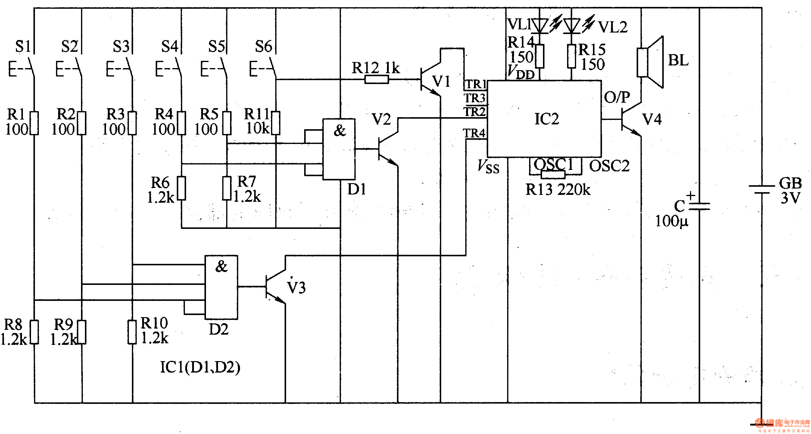
The three-tone electronic doorbell circuit includes a coding trigger circuit, a multi-tone generator, and an audio amplifier circuit, as illustrated in Figure 3-110. The coding trigger circuit is made up of buttons S1-S6, two four-input AND gates (D1, D2)...
M1 is a clamp connected to the 24V (dc or ac) power from the gate opener. The diode bridge rectifies the alternate voltage (should the opener use dc current, it merely adjusts the positive and negative rail to match...
Problems can arise with USB hubs powered from a PC when devices connected to them draw excessive current. This situation often occurs with devices that use USB cables that are either too long or too thin, leading to voltage...
The Raspberry Pi single-board computer (SBC) has garnered significant attention for being a complete system priced under $50. However, it is not the most affordable computing device available. For only $13.50, a mini computer that connects to a PC's...

An AC-triggered multitone, polyphonic doorbell that plays eight melodious tunes for a duration of two minutes. Each button press activates a new tone that continues until the melody concludes. The circuit is designed to be simple and operates on...
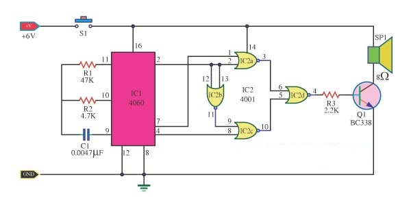
The doorbell sound circuit produces a two-tone sound. The circuit operates with switch S1. The integrated circuit IC1 functions as a frequency division circuit and generates sound frequencies through components C1 and R1. The audio signal is transmitted from...