
Arduino Make your own hardware

The circuit design for the electronic die project will involve the following components:
1. **Microcontroller**: An Arduino Uno R3 or Arduino Nano V3 will serve as the central processing unit, providing the necessary I/O ports for connecting LEDs and resistors.
2. **LEDs**: Seven individual light-emitting diodes will be used to represent the faces of the die. Each LED will be connected to a digital output pin on the Arduino.
3. **Resistors**: Seven 680-ohm resistors will be placed in series with each LED to limit the current and prevent damage to the LEDs.
4. **Breadboard**: A standard breadboard will be utilized for assembling the circuit without soldering. The breadboard allows for easy modification and testing of the circuit.
5. **Power Supply**: The Arduino will be powered via a USB connection to a computer or a USB power adapter, eliminating the need for additional power sources.
6. **Switch**: A momentary push-button switch will be included in the circuit to initiate the rolling action of the electronic die.
The wiring configuration will involve connecting each LED's anode to a digital pin on the Arduino, with the cathode connected to ground through a resistor. The push-button switch will be connected to a digital input pin, enabling the Arduino to detect when it is pressed. The programming will include functions to initialize the LEDs, read the switch state, and generate random numbers to simulate the rolling of a die. The setup() function will configure the I/O pins, while the loop() function will handle the LED flashing sequence and the random number generation logic.
This project exemplifies the practical application of microcontrollers in creating interactive electronic devices, combining programming with hardware assembly to produce a functional and educational tool.The world is going nuts over the Raspberry Pi single-board computer (SBC) for being a whole system under $50. In reality though the Pi isn`t actually the cheapest computing device available. If you want really cheap how does $13. 50 sound for a mini computer that can plug into your PC`s USB port be programmed in C+ and let loose into the real worl
d connected to all sorts of crazy stuff Welcome to the world of the PC-programmable microcontrollers. CPUs are the show ponies of the computing world they strut around showing off their high clock speeds but on their own they`re totally useless: they need a whole motherboard`s worth of bits to connect to real-world devices.
On the other hand microcontrollers are compact self-contained bite-size devices that run their own complete computing device they have storage RAM and interface ports that work with sensors displays and switches. They run everything from fridges to cars and clock radios. Microcontrollers don`t run anywhere near as fast as CPUs the ones we`ll look at only clock at 16MHz but they`re not encumbered by layers of Windows operating system to strangle the life out of them either.
Microcontrollers allow you to create complex gadgets at a fraction of the cost of using individual or discrete integrated circuits. However if you`re going to use microcontrollers a good working knowledge of electronics is required this series is all about real-world computing in the truest sense.
Yep we`ll talk electronics theory get our inner geek on and look at voltages currents resistors and the like. But frankly I get bored with theory alone damn quick so this series will be all about getting your hands dirty and building stuff.
And to do that as quickly as possible we`re going to use the excellent Arduino series of expandable microcontroller boards. Arduino was created in 2005 by two Italian engineers Massimo Banzi and David Cuartielles with the goal of making it easier for students to learn how to program and grow their understanding of electronics and use it in the real world.
Today 300000 boards later Arduino has grown into a highly expandable system of low-cost microcontroller boards that can be used to build everything from electronic dice to web servers. Arduino boards plug in to your PC via USB and you program them using the free Arduino integrated development environment available from arduino.
cc. There are several different Arduino boards and many more third-party compatible versions available the most common official ones being the Arduino Uno R3 and the Arduino Nano V3. Both of these run a 16MHz Atmel ATmega328P 8-bit microcontroller with 32KB of flash RAM 14 digital I/O and six analogue I/O.
While 32KB doesn`t sound like much we`re not running Windows you don`t need as much as you think and you can easily add microSD/SD card storage for bigger tasks. You can buy the Australian-designed Arduino Uno R3-compatible Freetronics Eleven from Jaycar for $40 or pick up Chinese equivalents for under $20 on eBay.
For less complex one-off projects eBay has tiny Arduino Nano V3-compatible boards with the same controller USB connectivity and I/O count for just $13. 50 including shipping. If you`ve never built anything with electronics before the best way to learn is by doing. Each project we do will have a specific parts list but you`ll also need a basic set of tools you`ll use for everything available from Jaycar Electronics or elsewhere online.
For the time being we won`t do any soldering and the only power required will be a USB port or a USB power brick which greatly reduces the chances of you blowing yourself up. Most electrical engineers go weak at the knees when they see a breadboard it`s like a blank canvas to a painter.
It`s a reusable plug-in board that lets you create electronic circuits without having to solder. The one we`re using has three sections: two horizontal row sections top and bottom and a main centre section. The holes at the top and bottom are connected horizontally each row separate from the other with a gap between the two halves.
The centre section pins are connected vertically in columns separated by the horizontal well in the middle. A digital multimeter (DMM) allows you to measure stuff electrical voltage across components electrical current through circuits as well as the electrical resistance of components.
We recommend an auto-ranging DMM which means all you have to do is simply select volts current or resistance you don`t have to also select the correct meter range to read the result. DMMs come with leads the black one plugs into the COM socket and the red one into either the 10A socket or volts/ohms socket as appropriate.
Just quickly the reason for the two sockets for the red lead is because you measure the current through a circuit and the voltagea across or resistance of a component or device. You don`t want the meter to affect the circuit you`re measuring so the 10A current socket has very very low resistance (or impedance) so it doesn`t affect current flow while the volts/ohms socket has a very high impedance so as not to change or load down the component or voltage you`re trying to measure.
And finally never use a multimeter to try to measure the resistance of a component while the circuit is powered up at best the reading will be wrong and at worst you`ll blow up the meter and/or the component you`re trying to measure. Ideally you want to measure resistance in isolation to everything else. For this project you`ll need seven 680-ohm resistors. Resistors use a special colour code to identify their value displayed by a series of tiny coloured bands on the body.
In theory they should be enough to work out the resistor value. The problem is that most resistors now have very thin colour bands and a base background colour that makes them hard to read. So to be sure measure resistors with your multimeter. Switch the meter to ohms put the red lead into the volts/ohms socket connect one lead to one side of the resistor and the other lead to the other side.
Don`t hold the ends of the both leads with your fingers because with higher resistor values your skin`s own resistance will alter the reading. Tech law says that when you`re programming something for the first time you must do the Hello world` app.
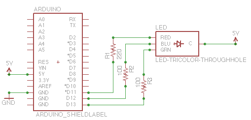
In Arduino land this is flashing the Arduino`s programmable light-emitting diode (LED) on and off. Bah! Why flash one LED when you can flash seven So I`ve designed an electronic die. The circuit is completely unoriginal but the special sauce is in the programming. Start off by installing the seven resistors and LEDs into the board. Resistors don`t have polarity which means they can go in either way around. LEDs are different and ours have two pins: one called an anode (A) the other a cathode (K). Look down at the top of the LED and one side will have a flat edge on it that`s the cathode pin. Follow the wiring diagram to build the circuit and take your time. We`ve used colour-coding on our big wiring diagram just to make it easier to see provided each wire is connected to the right location you can use whatever colours you want. The PCB-mount switch has little kinks in its pins. You`ll need to carefully flatten them out by squeezing them with your long-nose pliers and then it should press into the breadboard fairly easily.
One trick though press on the outer edge of the switch shell rather than the button itself just to ensure you don`t damage it. As for the wires you`ll need to bend them to get them into the Arduino`s jumper sockets but again take your time getting the wiring right now will save you hassles later on.
When you`re done all that`s left is to load our APC LED die software into the Arduino itself. Once you`ve got the hardware sorted out it`s time to program your Arduino. So far we`ve talked about apps and programming in Arduino apps are known as sketches and we`ll use this term from now on. To load a sketch into your Arduino grab the Arduino IDE (version 1. 0. 1) from arduino. cc/en/Main/Software. There are Windows Linux and Mac OS X versions but we`ll use the Windows version for simplicity. Unzip the archive and launch the arduino. exe` file. Download our APC sketch from apcmag. com/arduino. htm. Unzip the file to a folder head back to the Arduino IDE and from the top menu choose File > Open` navigate to the sketch folder and load in the APC_01_LED_die.
ino` file. Next plug your Arduino into your PC via a spare gUSB port. You`ll find the. INF driver software for Arduino-compatible boards in the arduinodrivers folder although Freetronics Eleven boards need a driver. INF file from. When installed Windows will assign a COM port to it note the number of that port. In the IDE menu select Tools > Board` and choose your Arduino type. Our project sketch works happily with Arduino Uno and Arduino Nano w/ ATmega328-compatible boards choose the appropriate option.
Next select Board > Serial Port` and the COM port from the driver installation. Now is the moment of truth you`ve checked your wiring against the diagram you`ve installed the driver loaded up the sketch into the Arduino and you`re ready to upload it to the board. In the IDE go to File > Upload`. This will compile your sketch into code and if there are no errors it`ll upload to your Arduino`s flash memory.
Provided you`ve followed the wiring precisely the LED die sketch should start operating. It only uses about 3KB of the 30KB or so of storage so we can create much larger sketches. We`ll look at this further next time but just briefly Arduino sketches have two compulsory procedures: setup() and loop(). The setup() procedure runs once as soon as the board is powered up. After that it drops into the appropriately named loop() procedure and runs around that infinitely until the power is removed.
You can create your own procedures although they must be referenced in either the setup() or loop() procedures otherwise they`ll never run. The first thing our electronic die does when it boots is light up all seven LEDs for two seconds to allow you to check your wiring.
This is done in the setup() procedure as we only need to do it once. After that it runs the main loop() procedure which starts with flashing the middle LED briefly twice a second to indicate that it`s ready to roll. Press and hold the button and the animated rolling sequence will begin you`ll see each outer LED flash alternately to simulate rolling.
When you let the button go the LEDs will flash up in random die numbers at a slowing rate until it settles on the final number. The final number will stay lit for three seconds before it blanks and goes back to flashing the centre LED again indicating it`s ready for the next roll`.
🔗 External reference
Related Circuits
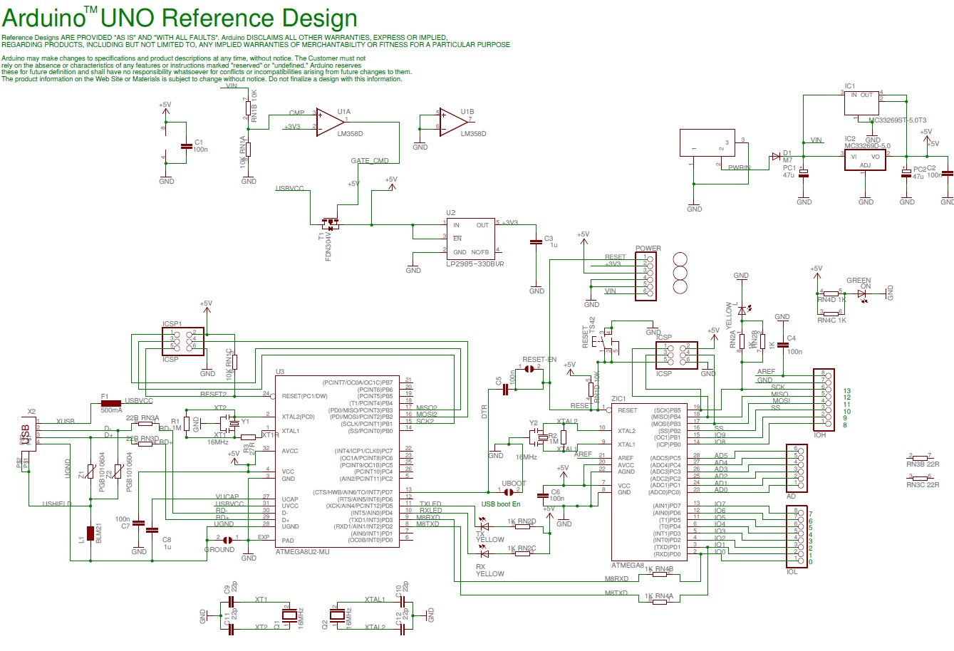
The Arduino Uno schematic diagram is available for viewing. The Arduino Uno is a microcontroller board that utilizes the ATmega328 chip. It features 14 digital input/output pins, of which 6 can function as PWM outputs, along with 6 analog...
The Arduino microcontroller board can supply a current of 40mA from its output connections, with digital outputs fixed at 5V for "ON" and 0V for "OFF." This current is suitable for LEDs, but devices like motors, solenoids, and high-brightness...
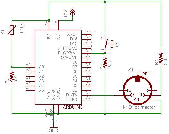
This page covers only the details of MIDI communication on the Arduino module. For a more general introduction to MIDI on a microprocessor, see the MIDI notes on Tom's physical computing site. MIDI, the Musical Instrument Digital Interface, is...
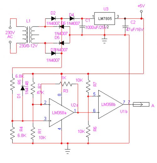
Create a temperature-controlled fan circuit using a 15V AC power supply instead of a 230V AC supply. Clarification is needed on whether it is necessary to change the triac and resistor in the provided diagram. Additionally, it is important...
The capability to control lights and fans wirelessly has transitioned from an expensive luxury to widely accessible consumer solutions. Nevertheless, creating a custom solution remains an engaging project for hobbyists and tinkerers. RobotGrrl has developed user-friendly libraries aimed at...
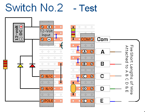
The prototype of Keypad Switch No. 2 was constructed using only the stripboard layout as a reference. If the layout has been accurately reproduced, a functional circuit will result. Once the layout is confirmed to be correct and a...