
Announcer DoorBell
The circuit described operates on a 24V power source, either AC or DC, which is supplied to M1, a clamp that stabilizes the input voltage for the subsequent stages. A diode bridge rectifier converts any AC voltage to DC while ensuring the correct polarity is maintained for the circuit's operation. The rectified voltage is then used to power a 24V relay, while a series resistor R1 limits the current to a 5V voltage regulator IC1. This regulator provides a stable 5V output to power the Nutchip, which is essential for the overall control logic of the circuit. The R3-C5 network connected to the Nutchip facilitates a proper reset, ensuring reliable operation.
The input stage features a double switch relay, RELAY1, which mirrors the state of the original photocell connected to M2. When the photocell detects an object, it energizes RELAY1, which in turn activates the output stage. One switch from RELAY1 is connected to M3, substituting the original photocell, while the other switch feeds the photocell signal to the Nutchip via input IN1, allowing the Nutchip to detect when an object enters its range.
The output stage includes RELAY2, driven by a transistor Q1, which is designed to operate at 24V DC. This choice prevents excessive load on the 5V regulator and ensures that the Nutchip operates within its power limits, eliminating the need for a heatsink. The design prioritizes thermal management, recognizing that reduced heat generation enhances the longevity of the circuit.
M4 serves as a clamp connected in parallel with an existing doorbell pushbutton, ensuring that the doorbell remains functional when RELAY2 is activated. The parallel configuration allows the doorbell to operate normally while also accommodating the added functionality of the photocell detection system.
To prevent nuisance ringing, particularly in high-traffic areas, the Nutchip incorporates logic states st11 and st12. State st11 ensures that the circuit only responds to the photocell signal when it is unobstructed, ringing the bell only once if an object remains in front of the sensor. State st12 introduces a 30-second "blind time" during which the circuit ignores further input, allowing for a more user-friendly operation. This timing can be adjusted based on specific application needs, providing flexibility in the design.M1 is a clamp connected to the 24V (dc or ac) power from the gate opener. The diode bridge rectifies the alternate voltage (should the opener use dc current, it merely adjust the positive and negative rail to match circuit polarity), in order to get the power required by the 24 V relay. The same potential, limited in current by the series resistor R1, feeds the 5V regulator IC1. The 5V stabilized voltage from IC1 powers the Nutchip; the R3-C5 network ensures proper RESET to the chip.
The input stage consists of a double switch relay, RELAY1. The original photocell's output connects to M2, therefore it powers the relay. RELAY1 clones the situation it sees on M2: it is energized when the photocell contact is closed, and it is released when the photocell contact is open. As a consequence, relay switches follow the original photocell behaviour. One of the two switches available in RELAY1 is brought to M3, in order to act as a replacement of the original photocell which is now connected to M2.
The other is used internally by the circuit in order to detect the photocell signal. This second switch connects to Nutchip input IN1, letting him to know when someone enters the photocell range. The output stage consists of the relay RELAY2 and its driver transistor Q1. We adopted a 24V dc relay in order not to overload the 5V regulator IC. Limiting the load to the Nutchip alone limits the power required from IC1, making an heatsink unnecessary.
It is important to limit heat as much as possible in circuits intended for continuous operation, as the less heat produced, the longer the circuit's life. The clamp M4 connects in parallel with the existing doorbell pushbutton (the doorbell rings when RELAY2 is energized).
Al the relay is in parallel, the doorbell will also continue to work as an ordinary doorbell. In case of many people crossing the gate, as in the case of a factory entrance during rush hours, a bell ringing continuously can be annoying. Another case is when someone stops right on the door threshold! In order to make circuit operation useful and enjoyable, the Nutchip acts with two countermeasures. State st11 wait for the photocell to be free from obstacles before continuing. Therefore, should someone stop in front of it, the bell rings only once. Moreover, state st12 iintroduces a 30 seconds "blind time" during which the circuit purposedly ignores any input.
This time proven to be fine with our tests, but you can set it to any other period you think appropriate. 🔗 External reference
Related Circuits
This circuit will light a lamp at a remote location when the doorbell switch is pressed. This circuit should only be used with the solenoid type doorbells; the electronic type that play tunes will not work here. It is...
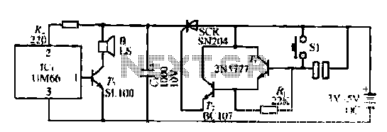
A few custom integrated circuits began to play music. When the song ends, no electricity flows through the thyristor, which then cuts off the light, causing the phototransistor to activate. The system is designed with a touchpad; each touch...

The electronic doorbell circuit consists of a pickup amplifier, a monostable trigger circuit, a pulse counter circuit, a music generating circuit, an audio amplifier circuit, and additional components. The pickup amplifier circuit is composed of a piezoelectric ceramic element,...
This project was designed for a boy who had a larger collection of electronic scrap, which he provided for the build. The project was completed over several evenings while balancing homework. The goal was to create a device that...
The most challenging aspect of this circuit was determining its title. It can be easy to overlook the sound of a doorbell while watching television; this circuit addresses that issue by providing a visual indication, such as a lamp....
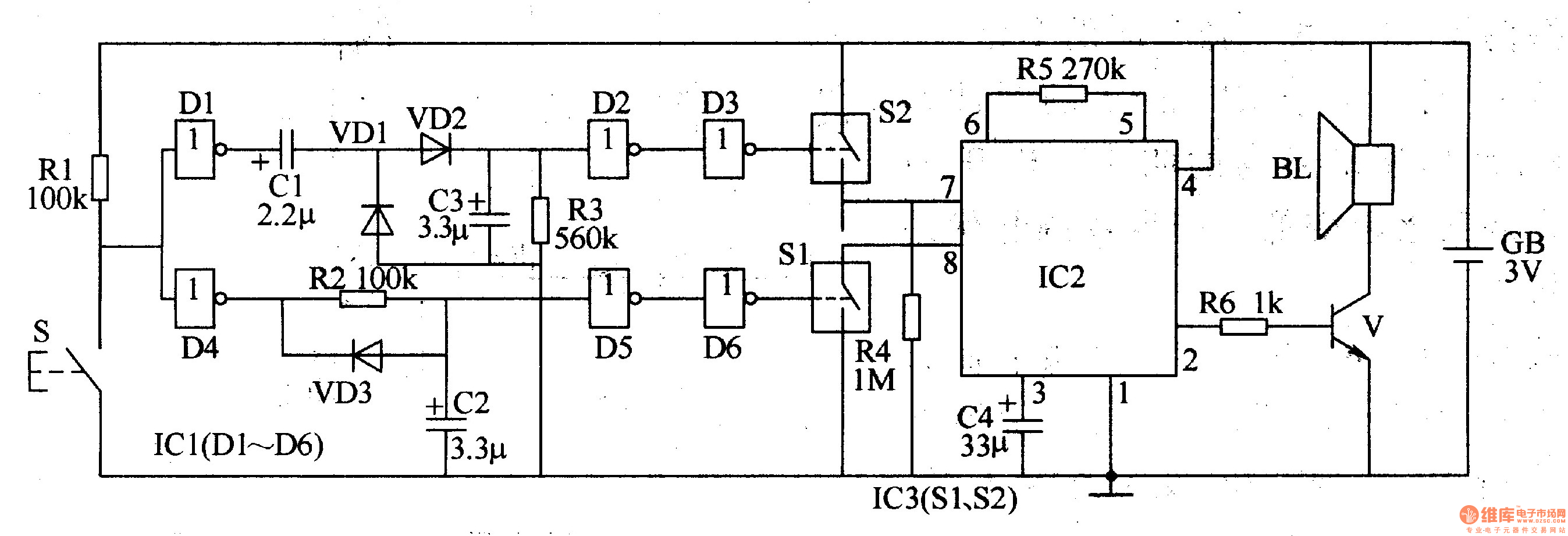
The two-tone electronic doorbell circuit comprises a trigger control circuit and a doorbell generating circuit, as illustrated in Figure 3-108. The trigger control circuit includes a doorbell button (S), resistors (R1-R3), electrical components (C1-C3), diodes (VD1-VD3), six NOT gate...