
Dancing LEDs
The circuit operates by detecting audio signals through a microphone, which is amplified by IC1A. This amplification is crucial for ensuring that even low-level audio signals can effectively trigger the LED illumination. The amplified signal is processed by IC1B, which detects the peaks of the audio waveform. These peaks are essential for timing the illumination of the LEDs, as they correspond to the beats or significant moments in the audio being played.
IC2, the ring decade counter, is responsible for sequencing the LEDs. It receives clock signals from IC1B, which synchronizes the LED illumination with the detected audio peaks. The counter allows for a sequential lighting pattern, making the visual output dynamic and engaging.
The additional circuit that drives the LED strips utilizes a constant current source design, which is advantageous for maintaining consistent brightness across multiple LEDs. Q1 and Q2 work together to provide a stable 10mA current to the LED strips, ensuring that the LEDs operate within their specified current ratings, thereby prolonging their lifespan and maintaining uniform brightness.
The switching transistor Q3 is pivotal in controlling the operation of each LED strip. By allowing for the connection of multiple LEDs in series, the design can accommodate different configurations based on user preference. The ability to adjust the number of LEDs per strip by changing the power supply voltage introduces flexibility, making the circuit suitable for various applications, whether powered by a battery or a wall transformer.
In summary, this circuit design not only provides an entertaining visual display synchronized with audio but also offers versatility in terms of LED configuration and power supply options, making it a valuable project for electronics enthusiasts and professionals alike.The basic circuit illuminates up to ten LEDs in sequence, following the rhythm of music or speech picked-up by a small microphone. The expanded version can drive up to ten strips, formed by up to five LEDs each, at 9V supply. IC1A amplifies about 100 times the audio signal picked-up by the microphone and drives IC1B acting as peak-voltage detector
. Its output peaks are synchronous with the peaks of the input signal and clock IC2, a ring decade counter capable of driving up to ten LEDs in sequence. An additional circuit allows the driving of up to ten strips, made up by five LEDs each (max. ), at 9V supply. It is formed by a 10mA constant current source (Q1 & Q2) common to all LED strips and by a switching transistor (Q3), driving a strip obtained from 2 to 5 series-connected LEDs.
Therefore one transistor and its Base resistor are required to drive each strip used. Adopting the additional circuit, only one item for R10, R11, Q1 and Q2 is required to drive up to ten LED strips. On the contrary, one item of R9 and Q3 is necessary to drive each strip you decided to use. Whishing to use a lower number of LEDs or LED strips, pin #15 of IC2 must be disconnected from ground and connected to the first unused output pin.
Example: Whishing to use a wall-plug transformer-supply instead of a 9V battery, you can supply the circuit at 12V, allowing the use of up to 6 LEDs per strip, or at 15V, allowing the use of up to 7 LEDs per strip. 🔗 External reference
Related Circuits
The LM3915 is a monolithic integrated circuit that senses analog voltage levels and drives ten LEDs providing a logarithmic 3 dB/step analog display. LED current drive is regulated and programmable, eliminating the need for current limiting resistors. The IC...
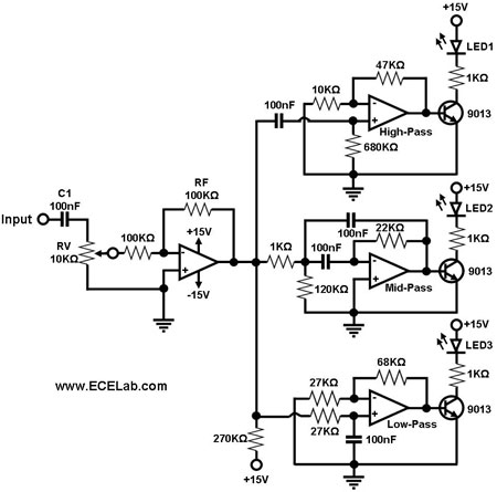
The simple circuit for converting an audio signal. The circuit basically consists of a buffer/amplifier stage and three filter circuits. The audio signal conversion circuit is designed to process audio signals efficiently while maintaining signal integrity. The circuit architecture includes...
The circuit below demonstrates how to power one or two LEDs from a 120-volt AC line. It utilizes a capacitor to reduce the voltage and a small resistor to limit the inrush current. As the capacitor needs to allow...
In this electronic roulette wheel, the 555 timer functions as a pulse generator with a fading frequency. The 4017 counter activates LEDs sequentially in the selected string, while a D-type flip-flop (4013 IC) serves as a divider by two...

Efficient automatic solar garden lights circuit with minimal components. The advantage is that it operates completely automatically, with the solar panel serving as a light detector. The efficient automatic solar garden lights circuit is designed to provide illumination using renewable...
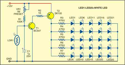
This sunlight-controlled lamp utilizes a light-dependent resistor (LDR) as the sunlight sensor and comprises a total of 25 high-brightness white LEDs. Each row of LEDs is connected in series with separate resistors. The operation of the circuit is straightforward....
Warning: include(partials/cookie-banner.php): Failed to open stream: Permission denied in /var/www/html/nextgr/view-circuit.php on line 713
Warning: include(): Failed opening 'partials/cookie-banner.php' for inclusion (include_path='.:/usr/share/php') in /var/www/html/nextgr/view-circuit.php on line 713