
Sound To Dancing Lights Converter With 9013 Transistor
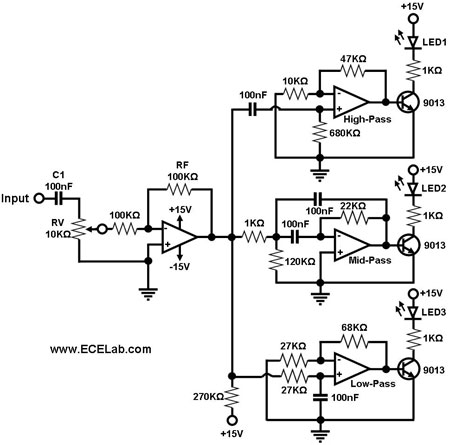
The audio signal conversion circuit is designed to process audio signals efficiently while maintaining signal integrity. The circuit architecture includes a buffer/amplifier stage, which is crucial for isolating the input signal from the output load and providing necessary gain. This stage typically employs operational amplifiers (op-amps) configured in a non-inverting arrangement to achieve high input impedance and low output impedance, ensuring minimal loading effect on the previous stage.
Following the buffer/amplifier stage, the circuit incorporates three distinct filter circuits. These filters serve to manipulate the frequency response of the audio signal, allowing specific frequency ranges to be enhanced or attenuated. The design may include a low-pass filter to eliminate high-frequency noise, a high-pass filter to remove low-frequency hum, and a band-pass filter to isolate a specific frequency range of interest. Each filter can be implemented using passive components such as resistors, capacitors, and inductors, or active components like op-amps, depending on the desired performance characteristics.
The overall design of this audio signal conversion circuit aims to optimize sound quality and fidelity by carefully selecting component values and configurations. Proper layout and grounding techniques are also essential to minimize interference and ensure stable operation. This circuit finds applications in various audio processing systems, including mixers, equalizers, and amplifiers, where precise audio signal handling is critical.The simple circuit for converting an audio signal. The circuit basically consists of a buffer/amplifier stage and three filter circuits: a .. 🔗 External reference
Related Circuits
The TDA8444 is a digital-to-analog (D/A) converter integrated circuit (IC) produced by Philips. It is designed to convert digital signals into analog signals. The TDA8444 IC utilizes a 16-pin dual in-line package, with specific pin functions and data outlined...

The 24V to 12V converter schematic is straightforward; however, it is important to ensure that all components, including transistors and integrated circuits, are adequately heat dissipated and electrically insulated from metal surfaces. The schematic diagram is derived from the...
This surround-sound decoder is based on the "Hafler" principle, first discovered by David Hafler sometime in the early 1970s. The original idea was to connect a pair of speakers as shown in Figure 1, for use as the rear...
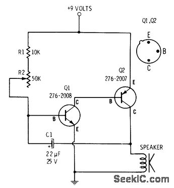
R2 controls the charging speed of capacitor C1. At a specific charge level, C1 triggers transistors Q1 and Q2, which release a 9-volt pulse. This pulse generates a clicking sound. The discharge process of the capacitor involves it charging...
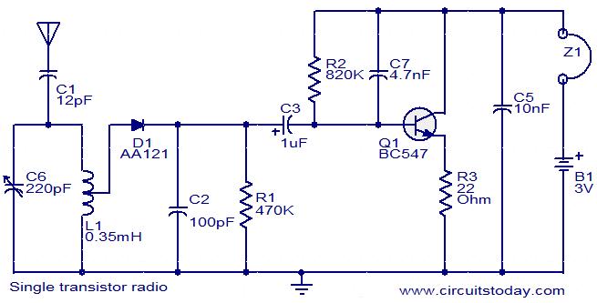
The circuit diagram of a simple radio that uses one transistor and a few other passive components. Component: Diode, Capacitor, Inductor, Resistor. The circuit design for a simple radio receiver typically incorporates a single transistor as the active amplification element,...

The circuit serves as a signal source for calibration level meters or sensor-driven differential transformers. The oscillation frequency is determined by the 74HC04, producing a frequency of 1 kHz through resistor R. The supply voltage of the circuit changes...
Warning: include(partials/cookie-banner.php): Failed to open stream: Permission denied in /var/www/html/nextgr/view-circuit.php on line 713
Warning: include(): Failed opening 'partials/cookie-banner.php' for inclusion (include_path='.:/usr/share/php') in /var/www/html/nextgr/view-circuit.php on line 713