
Dark and Light Activated Relay
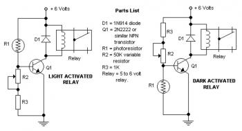
The circuit employs a potentiometer to adjust the trigger level for activating various components, providing flexibility in operation. The choice of diode is critical; while the 1N914 is acceptable for low power applications, the recommendation to use a 1N4001 diode is prudent for enhancing reliability and performance in the circuit. The inclusion of alternative transistors such as NTE123A, ECG123A, and PN100 allows for component substitution based on availability and performance characteristics.
The staircase light circuit operates with an adjustable timer, enabling users to customize the duration for which the light remains on after activation, enhancing user convenience in stairwell navigation. The sound detection mechanism utilizes a condenser microphone, which is sensitive to acoustic signals, converting them into electrical signals. The signal processing is managed by the BC549 transistor, which amplifies the input sound signals. The amplification stage is crucial for ensuring that even quiet sounds can trigger the relay to activate the connected load.
The voice-operated relay circuit is designed to respond dynamically to sound inputs, with the relay acting as a switch that connects or disconnects the load based on the detected sound level. This functionality can be applied in various applications, such as automated lighting systems or sound-activated devices.
The automatic emergency light circuit, controlled by an integrated circuit, demonstrates advanced features such as automatic activation during power outages and battery management. This ensures that the light remains operational when needed most, providing safety and security in emergencies. The relay's de-energized state during power absence indicates that the system is designed to conserve energy while remaining ready for activation.
The sound-activated switch circuit's adjustable sensitivity expands its usability in different environments, making it suitable for applications ranging from simple home automation to complex interactive systems. Lastly, the wireless car alarm system enhances vehicle security through the use of FM radio technology, allowing for remote monitoring and control, which can be vital for protecting vehicles from theft or unauthorized access. Overall, these circuits exemplify practical applications of electronic components in everyday scenarios, showcasing versatility and innovation in design.The potensiometer adjust the trigger on` level. The diode in the circuit diagram shows to be 1N914. This is ok if you have a light-duty relay, also the 1N914 is a signal diode so actually does not qualify. Use a 1N4001 (or better) instead. A couple of substitutes for the 2N2222 transistor are: NTE123A, ECG123A, PN100, etc. Tags: 1N914, 2N2222, dar k activated switch circuit, dark sensor, ECG123A, light activated relay, light activated relay circuit, light activated switch, light activated switch circuit, light sensor, NTE123A, photoresistor, PN100, This is the circuit diagram of staircase light with automatic switch off. It based on timer which is can be adjusted with the needs of the time of walking (climbing up and going down) on the staircase.
We have been all acquainted with all the electrical wiring design that joins an electrical bulb with two. How this sound activated light works: The condenser microphone fitted inside a position to catch the sound and generates AC signals, which pass by means of DC blocking capacitor C1 for the base of transistor BC549 (T1).
Transistor T1 as well as transistor T2 amplifies the sound signals and delivers current pulses within the collector. This is the circuit diagram of a voice operated relay. It similar with sound activation switch circuit which will turn on and turn off (connect and disconnect) the switch depending on the sound input.
The output switch of this circuit is act by a relay. Component Parts list: R1, R7 1K R2, R4, R8 10K. The schematic diagram shown right here is the automatic switching-on emergency light circuit which is controlled using IC. The most important capabilities of this circuit are: automatic switching-on of the light on main power failure and battery charger with overcharge protection.
When mains electrical power is absent, relay RL2 is in deenergised state, feeding DC. This is a sound activated switch circuit. It`s will turn on and turn off based on a loud sound such as clapping your hands. You can adjust the sensitivity (how loud of a sound will activate the circuit) from a pin drop to a Mack Truck Horn. Very practical for a variety of projects. Add. This circuit is a wireless car alarm system that is built using two circuit modules, namely modules of transmitter and receiver modules.
This circuit works on FM radio waves. Car alarms can be used on vehicles that have a 6-12VDC power supply. You can use the voltage stabilizer if your car power supply is too. 🔗 External reference
Related Circuits
It allows car headlights to flash on and off simultaneously or alternately. Components: 555 IC, transistor, resistor, relay, polarized capacitor. The circuit utilizes a 555 integrated circuit (IC) in a monostable or astable configuration to control the flashing of car...
This simple circuit, as shown in the schematic diagram, activates a switch using sound. It can be utilized for various applications, such as automatic sound-controlled disco lights or a car's LED light show. The transistor Q1 amplifies the audio...
Most thefts occur after midnight when individuals enter the second phase of sleep known as paradoxical sleep. An energy-saving circuit has been designed to deter theft attempts by illuminating potential entry points, such as the kitchen or backyard, around...
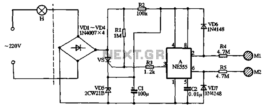
The circuit illustrated in the figure features a dashed line on the left, representing a standard lighting circuit, while the right side is responsible for the dual functionality of touch activation using the NE555 timer. Components VD1 through VD4...
In this circuit, two transistors are configured as a high-gain compound pair. Transistor T1 is likely a 2N2222A, while T2 is identified as a BC108. The current gain is calculated as the product of the beta values of each...
This is a Courtesy Light Extender for vehicles. It extends the ON time of the interior lights when a door is closed, allowing passengers to see where they are seated. The Courtesy Light Extender circuit is designed to enhance the...