
Sound-Activated Lamp (Relay/Switch)
")
This circuit operates on the principle of sound detection and signal amplification. The microphone picks up ambient sound, converting it into an electrical signal. The transistor Q1, typically configured as a common-emitter amplifier, boosts this signal to a sufficient level. The resistor R1 plays a crucial role in setting the sensitivity of the circuit; by adjusting its value, the threshold at which the circuit responds to sound can be fine-tuned.
Once the amplified signal exceeds the predetermined threshold, it activates the silicon-controlled rectifier (SCR), which acts as a switch. The SCR allows current to flow through the load, in this case, lamp I1, effectively turning it on. This configuration is particularly useful in applications where visual indicators are needed in response to sound, such as in entertainment or decorative lighting systems.
For applications requiring control of higher power devices, substituting lamp I1 with a relay is recommended. The relay can handle larger currents and voltages, making it suitable for controlling high-wattage lamps or other electrical devices. The inclusion of a 1N4007 diode across the relay coil is essential to protect the SCR from voltage spikes generated when the relay coil is de-energized. This diode provides a path for the back EMF, ensuring reliable operation and longevity of the SCR within the circuit.
In summary, this sound-activated switch circuit is versatile and can be adapted for various applications, from simple lighting control to more complex automation systems, emphasizing the importance of component selection and configuration in achieving desired performance outcomes.This simple circuit shown int the schematic diagram actives the switch using sound. We can use this circuit for various applications, such as automatic (sound-controlled) disco light or car`s LED light show. The Q1 amplify the audio from mic. The R1 is used to adjust the peak of signal to greater than about 0. 7 volts, act as sensitivity adjuster. A certain level, the signal coming from microphone, after amplification by Q1, will trigger the SCR and light lamp I1. If we change the lamp with a relay, then we can get a sound-activated relay/switch, which can be used to control more powerful / high wattage high voltage lamps.
If we use a relay, place a 1N4007 diode in parallel with the relay coil to prevent the back-emf from relay coil destroying the SCR. Here is the schematic diagram of the circuit: 🔗 External reference
Related Circuits
The purpose of this circuit is to power a lamp or other appliance for a specified duration (30 minutes in this case) and then automatically turn it off. This functionality is particularly useful for reading in bed at night,...
A neon lamp or tube lamp requires high voltage to initiate the ionization of the gas contained within the tube. Once ionization takes place, the voltage decreases to approximately 40 volts. Neon lamps operate on the principle of gas discharge,...
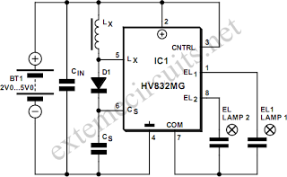
An EL lamp is a solid-state, low-power, uniform area light source. Due to its thin profile (as thin as 0.3 mm) and its capability to be manufactured in various sizes and shapes, EL lamps serve as an ideal solution...
The optically-controlled circuit plays a crucial role in urban street lighting and corridor illumination. By utilizing this circuit, lighting lamps can be automatically turned on and off based on ambient light levels, thereby reducing the need for manual control,...

The purpose of this circuit is to power a lamp or other appliance for a specified duration (30 minutes in this case) and then automatically turn it off. This feature is particularly useful for reading in bed at night,...
The saving lamp circuit features two main types: glass cover and exposed. The glass cover variants include three series: spherical, cylindrical, and processing types. The first two series consist of four variations: transparent, carved, engraved, and white. These lamps...