
With NE555 make double touch light switch 2
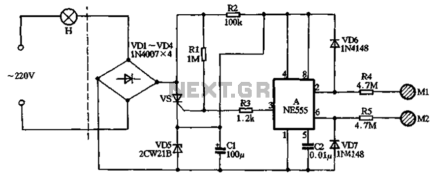
The described circuit operates as a touch-sensitive lighting system utilizing the NE555 timer IC. The primary function of the circuit is to control the lighting based on human interaction, specifically through capacitive sensing. The bridge rectifier formed by diodes VD1 to VD4 allows for the conversion of AC voltage to DC, ensuring that the circuit can operate effectively under varying input conditions. The NE555 timer is configured in a monostable mode, where it generates a single output pulse in response to a triggering event.
The use of capacitors C1 and resistors R2 and R3 in conjunction with the rectifier diodes ensures stable voltage regulation essential for the reliable operation of the NE555 timer. The design allows for a consistent 6V output, which is critical for the timer's functionality, preventing voltage drops that could interrupt operation.
The touch sensitivity mechanism is achieved through the electrodes M1 and M2, which detect the presence of a finger through capacitive coupling. The induced noise signal is critical for triggering the timer, allowing for a responsive and user-friendly interface. The integration of rectifying diodes VD6 and VD7 ensures that the signals are appropriately conditioned for the timer's input requirements.
This circuit is well-suited for applications where touch activation is preferred, such as in lighting systems for homes, decorative installations, or interactive displays. The simplicity of the design, combined with the functionality provided by the NE555 timer, makes it an effective solution for creating touch-sensitive lighting systems. Circuit shown in Figure, the dashed line in FIG left portion as an ordinary lighting circuit, the right part of the production of the double bonds of touch with NE555 3-3 Switc hing lights. VD1 ~ VD4 form a bridge rectifier circuit, vs and VD5 constituting the main circuit switch. When vs turned on, the lights: vs when blocked, lights out. When vs in blocking state, 220V AC by VD1 ~ VD4 rectified by R2, VD5 and CI composition regulator circuit, Cl obtain about 6V DC voltage at both ends, for the time base manifold A electricity. When vs in the on -state when the alternating current through the VD1 ~ VD4 rectified by vs and VD5 constitute a loop, ends in CI can maintain 6V left and right DC voltage output.
Therefore, when the base integrated circuit DC operating voltage will not vs conduction fell. A time base circuit connected to the RS flip-flop here, when a finger touches the electrode pad Ml, human induced noise signal by R4 injection time base circuit trigger terminal 2 feet, and by the end of the trigger VD6 rectifier 2 feet to give a negative pulse trigger, time base circuit is set, the output of almost 3 feet high output power, and this time vs Rl obtained by the opening of the trigger current, light hair H powered light. Turn off the lights when needed, just fingering a lower electrode sheet M2, this time the body induced noise signal by the R5 and injected through VD7 rectified so that the time base circuit threshold terminal 6 feet to give a positive signal pulse trigger, time base circuit reset output terminal 3 pin output low, Rl positive trigger voltage is provided by the group R3 when the circuit is shorted to ground pin 3, vs loss of trigger voltage when the AC had mold that is turned off, the lamp H goes out.
Related Circuits
This stand-light features a 1000 µF capacitor (C5) that connects the dynamo to the lights. The capacitor cuts off power to the lights at low speeds. While this effect may be negligible for a bottle dynamo, it could be...
This circuit was adapted from the Toggle Switch Debounced Pushbutton by John Lundgren. It is useful where the load needs to be switched on from one location and switched off from another. Any number of momentary (N/O) switches or...
A 1984 F-350 crew cab with a 460 engine has a malfunctioning fuel gauge and is unable to pump fuel from the front tank. The initial troubleshooting steps included replacing the switch in the dashboard and the switch on...
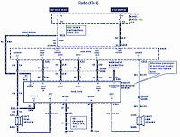
The section of the 1996 Ford Windstar wiring diagram includes details on power distribution, common connections, rear circuits, ignition systems, the fuse panel, battery connections, instrument illumination, radio wiring, left rear speaker connections, remote headphone module, solid-state components, and...
For this special Halloween project, a spooky candy bowl was created that lights up when an unsuspecting trick-or-treater reaches in. While similar devices exist, many utilize complicated proximity sensors. The approach taken here is simpler, making it a suitable...
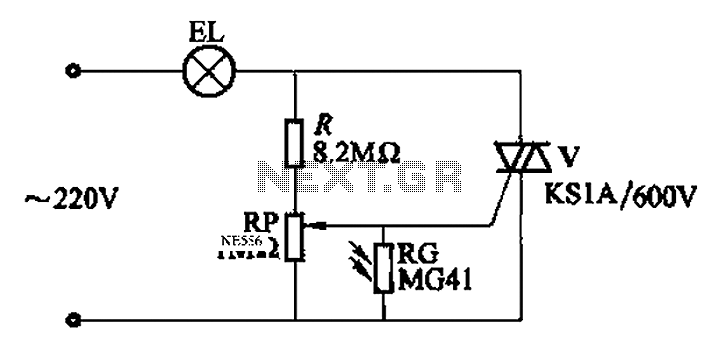
An automatic light control circuit is designed to illuminate a lamp when it is dark and to turn off the light at daybreak. The circuit, as shown in Figure 2-86, employs bidirectional thyristor tubes and features a straightforward design....