
Dark Seeker - TV-to-Scope Converter
The VGA-to-Scope converter circuit facilitates the conversion of VGA signals into a format suitable for oscilloscope analysis. The simplification of the circuit design, particularly the removal of op-amp buffers and inverters, enhances the reliability and reduces the complexity of the overall system. The use of a 1 Megohm potentiometer connected to a 5V supply serves as an adjustable charging mechanism for the capacitor, enabling fine-tuning of the charge rate to optimize performance.
In this configuration, the capacitor plays a crucial role in storing the voltage level of the VGA signal for analysis. By adjusting the potentiometer, the user can control the time constant of the charging circuit, which directly affects the signal representation on the oscilloscope. The trigger signal from the 555 timer is essential for synchronizing the discharge of the capacitor, ensuring that the oscilloscope captures the correct signal waveform at the appropriate time.
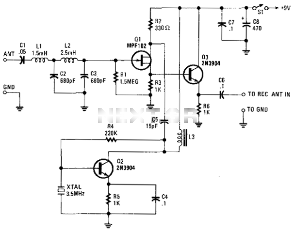
This design provides a more user-friendly approach to interfacing VGA signals with oscilloscopes, allowing for easier troubleshooting and analysis of video signals. The elimination of unnecessary components not only simplifies the circuit but also reduces potential points of failure, thus enhancing overall reliability.If you refer to the above schematic, you`ll notice that the VGA-to-Scope converter has been simplified, while op-amp buffers and inverters were simply eliminated. The continuous current supply to charge up the capacitor can be replaced by a 1Meg pot from 5V to charge up the capacitor constantly.
If you placing the pot at the right position, the ca pacitor will be charge up, and the trigger signal stopped the 555 to discharge the capacitor. We aim to transmit more information by carrying articles. Please send us an E-mail to wanghuali@hqew. net within 15 days if we are involved in the problems of article content, copyright or other problems. We will delete it soon. 🔗 External reference
Related Circuits
The TLD 5085EJ is a smart LED buck converter featuring an integrated power switch, designed to drive a load current of up to 1.8A with excellent line and load regulation. This device is specifically intended for stepping down input...
The VLF Converter is designed to receive signals for general coverage in shortwave receivers. It can pick up various unusual signals on frequencies below 15 kHz. This converter effectively transforms frequencies ranging from 0 to 250 kHz into a...

This circuit operates effectively across a broad frequency spectrum. XTAL 1 serves as a fundamental-frequency crystal. Tl and CI are adjusted to match the input frequency. This circuit can be utilized as a straightforward shortwave converter for AM radios,...
A DC/DC step-up converter is suitable for use in battery-powered equipment. This converter can be employed to generate supply voltages for internal circuits. The DC/DC step-up converter, also known as a boost converter, is a critical component in various electronic...
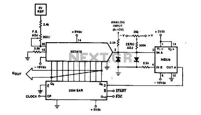
The time IO-bit conversion operates at 3.3 MHz with a clock signal. This converter utilizes a 2504 12-bit register in successive approximation mode, where the conversion signal for the short-cycle end is derived from the first bit utilized in...

A project is underway that necessitates the conversion of a 0-10V DC supply into a linear frequency range in the form of a square wave. The project involves designing a circuit that takes a direct current (DC) voltage input ranging...