
Vlf Converter
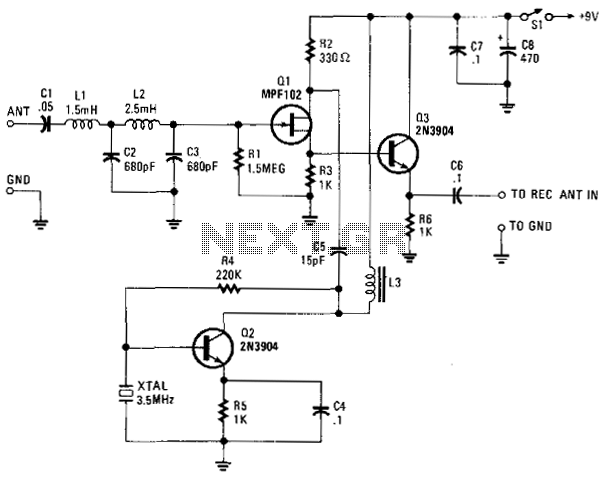
The VLF Converter circuit operates as a frequency translator, enabling the reception of very low frequency (VLF) signals by shifting them into a range compatible with standard shortwave receivers. The initial signal reception occurs via a short whip antenna, which captures low-frequency signals. These signals are filtered through a low-pass filter, comprising inductors L1 and L2 along with capacitors C2 and C3, which attenuates higher frequency noise and allows only the desired frequency range to pass to the RF amplifier Q1.
The RF amplifier Q1 boosts the strength of the filtered signal before it is mixed with a local oscillator signal generated by Q2. The mixing process occurs within transistor Q3, which combines the amplified VLF signal with the stable 3.5 MHz signal. The mixing results in the generation of intermediate frequencies that fall within the range suitable for the shortwave receiver.
The RF choke L3 is a critical component in this circuit, as it provides necessary inductive loading to Q3, ensuring optimal performance. It is important that L3 is tuned to resonate slightly above 3.5 MHz, which helps maintain the stability and efficiency of the mixing process. The adjustable coil allows for fine-tuning, accommodating variations in the circuit or antenna characteristics.
Finally, the output signal is extracted from the emitter of Q3 through capacitor C6, which serves to block any DC component, allowing only the AC signal to pass to the subsequent stages of the receiver. This design effectively enables the reception of a wide range of low-frequency signals, enhancing the capabilities of standard shortwave receivers in the process. The VLF Converter can be used to pick up signals for the general coverage of shortwave receivers. A number of unusual signals can be heard on frequencies below 15 kHz. This converter will convert frequencies from 0 to 250 kHz to 3 500 to 3 750 kHz so that the LF- and VLF-band segments can be received on an amateur or shortwave receiver that covers 3 500 to 4 000 kHz, Signals from a short whip antenna (8 to 10 feet) are coupled through low-pass filter L1/L2/C2/C3 to RF amp Ql. Q3 mixes these signals with a 3.5-MHz signal from Q2 and associated components C4, R5, R4, and 3.5-MHz XTAL.
L3 is an RF choke that presents an inductive load to Q3. It should be resonant somewhat above 3.5 MHz when placed in the circuit. An adjustable coil of about 30 to 100 should be sufficient. The converter output is taken from the emitter of Q3 through C6. 🔗 External reference
Related Circuits
In electronics, a digital-to-analog converter (DAC or D-to-A) is a device that converts a digital code, typically in binary format, into an analog signal, which can be in the form of current, voltage, or electric charge. DACs are utilized...
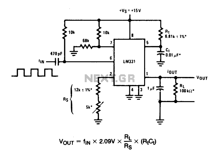
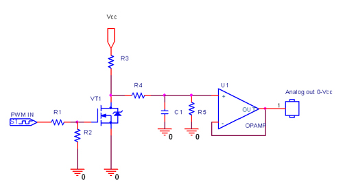
In these applications, a pulse input at a specified percentage is differentiated by a capacitor-resistor (C-R) network. The negative-going edge at pin 6 triggers the input comparator, activating the timer circuit. Similar to a voltage-to-frequency (V-to-F) converter, the average...
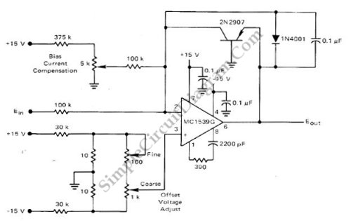
This low-cost logarithmic converter is constructed using an operational amplifier (op-amp) and a transistor. The circuit utilizes a Motorola MC1539G op-amp connected to a PNP transistor. The logarithmic converter circuit is designed to convert linear input signals into logarithmic output...
This converter allows reception of signals below 500 kHz on a 3.5 to 4 MHz HF receiver. It should therefore be useful for those with receivers that do not receive the lower frequencies. Again the converter uses the popular...
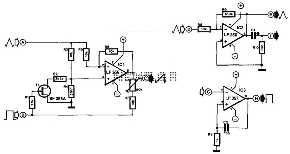
Simple function generators typically produce sinusoidal, rectangular, and triangular waveforms, but rarely generate sawtooth waveforms. The circuit depicted in Fig. 21-4(a) generates a sawtooth signal from rectangular and triangular signals. The quality of the sawtooth output is influenced by...
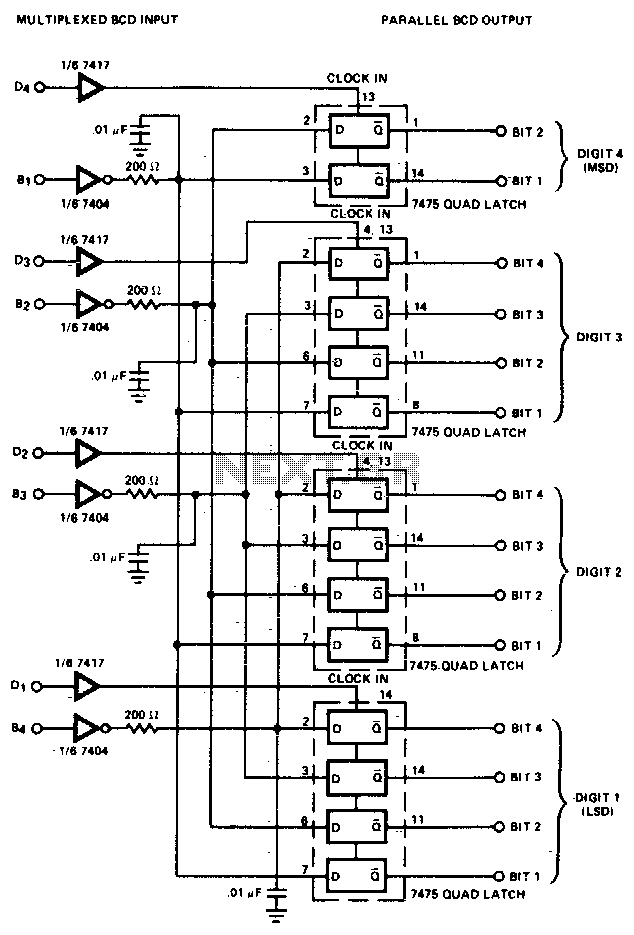
The converter is composed of four quad bistable latches that are activated in the correct sequence by the digit strobe output from the LD110. The complemented outputs (Q) of the quad latch set represent the state of the bit...