
555 timer as a voltage to frequency converter

The project involves designing a circuit that takes a direct current (DC) voltage input ranging from 0 to 10 volts and converts it into a square wave output with a frequency that varies linearly with the input voltage. This type of circuit is commonly used in applications such as signal modulation, control systems, and frequency generation.
To achieve this, a voltage-controlled oscillator (VCO) can be employed. The VCO will generate a square wave output whose frequency is directly proportional to the input voltage. The circuit can be designed using operational amplifiers (op-amps) and other discrete components.
The primary components of the circuit include:
1. **Input Stage**: This stage will include a voltage divider or buffer to ensure that the 0-10V input signal is properly conditioned for the VCO.
2. **Voltage-Controlled Oscillator (VCO)**: A VCO can be implemented using an op-amp configured in a relaxation oscillator configuration. The frequency of oscillation can be set by selecting appropriate resistor and capacitor values in the feedback loop.
3. **Output Stage**: The output square wave can be further processed or buffered to match the desired load or interfacing requirements.
The frequency range of the output square wave should be carefully calculated based on the specifications of the project. For instance, if the requirement is to achieve a frequency range from 1 Hz to 10 kHz with a 0-10V input, the values of the resistors and capacitors in the VCO circuit must be chosen accordingly to ensure the linear relationship between input voltage and output frequency.
Additional considerations include power supply decoupling, signal integrity, and potential filtering to eliminate any unwanted harmonics or noise from the square wave output. Proper simulation and testing of the circuit will be essential to validate performance before final implementation.Hi All, I am currently working on a project that requires a 0-10V DC supply to be converted into a linear fequency range - square wave. for instance.. 🔗 External reference
Related Circuits
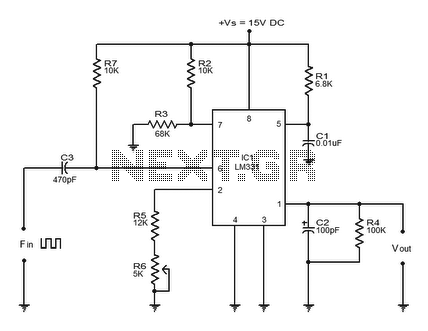
The LM331 is a precision voltage-to-frequency converter developed by National Semiconductors. This integrated circuit (IC) has various applications, including analog-to-digital conversion, long-term integration, voltage-to-frequency conversion, and frequency-to-voltage conversion. Its wide dynamic range and excellent linearity make it suitable for...
The following circuit illustrates a Boost Converter Circuit Diagram. This circuit is based on the 555 IC. Features: it only requires off-the-shelf components. The Boost Converter is a type of DC-DC converter that steps up the input voltage to a...
The RF engineer occasionally needs to find an instrument that can reliably and quickly test a low-frequency quartz crystal unit. This equipment is often challenging to locate, leading engineers to consult electronic circuits handbooks for schematics that can perform...

The circuit detailed in this document is designed to produce up to 30 kilovolts or more from a low-voltage DC source using a flyback transformer (LOPT) salvaged from a black-and-white or color television or computer monitor. With a typical...
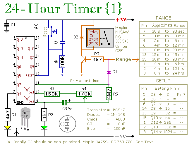
A pair of multi-range timers capable of timing periods up to 24 hours and beyond. Both versions are fundamentally similar, with the primary distinction being that Version 1 energizes the relay when the time expires, while Version 2 de-energizes...
High voltage electrolytic capacitors in valve equipment can deteriorate if the equipment is unused for an extended period. This deterioration manifests as reduced capacitance and significantly increased leakage current. In some instances, the capacitor may become nearly short-circuited. Using...