
Data Based IQ Demodulator

The IQ_Demod project provides a comprehensive framework for analyzing and simulating demodulation processes using advanced behavioral modeling techniques. The core of this project revolves around the IQ_Demod_Setup and IQ_Demod_Data components, which facilitate the creation of sophisticated models within the ADS environment. The schematic "IQ_demod_ckt.dsn" serves as the primary demodulator architecture, designed to replicate the behavior of a real-world demodulation system.
The modulator's design is modular, consisting of various sub-circuits that enhance functionality and performance. The "MixerGilCel.dsn" sub-circuit is responsible for mixing operations, while "phase_shift.dsn" introduces necessary phase adjustments, and "Wilkinson.dsn" is likely utilized for impedance matching or power splitting.
Behavioral modeling is a key aspect of this project, allowing for the extraction of performance metrics through the "Setup_IQ_demod_ckt.dsn" file. This file enables the simulation to produce datasets that encapsulate the demodulator's behavior under different conditions, such as those represented in "circuit_level_ramp.ds" and "behavioral_level_ramp.ds." These datasets provide insights into the performance of the demodulator with time-varying I_Q waveforms, essential for analyzing dynamic signal conditions.
The project also includes specific configurations for Quadrature Amplitude Modulation (QAM) through the "circuit_level_QAM.dsn" and "behavioral_level_QAM.dsn" schematics. These schematics allow for the simulation of 16 QAM signals, which are critical in modern communication systems due to their efficient use of bandwidth.
Figures included in the project documentation provide visual validation of the simulation results, comparing circuit-level and behavioral-level outputs. The strong correlation between these outputs underscores the reliability of the models created and their applicability in real-world scenarios. The project exemplifies the integration of circuit design and behavioral modeling, contributing to advancements in demodulation technology.The IQ_Demod project illustrates the use of the IQ_Demod_Setup and IQ_Demod_Data components in ADS. These components are part of the ADS behavioral model suite found under the System - Data Models palette. "IQ_demod_ckt. dsn" is a schematic for the demodulator of interest. This demodulator follows the topology of the system-level demodulator constructed. The modulator is constructed of the sub-circuits "MixerGilCel. dsn", "phase_shift. dsn", and "Wilkinson. dsn". "Setup_IQ_demod_ckt. dsn" is a for a behavioral model extraction of "IQ_demod_ckt. dsn" using IQ_Demod_Setup. The result is in the dataset "Setup_IQ_demod_ckt. ds". "circuit_level_ramp. dsn" is a schematic for a circuit level Circuit Envelope simulation of "IQ_demod_ckt. dsn" with I_Q waveforms that have time-varying amplitude. The result is in the dataset "circuit_level_ramp. ds". "behavioral_level_ramp. dsn" is a schematic for a behavioral level Circuit Envelope simulation with I_Q waveforms that have time-varying amplitude. "IQ_demod_ckt. dsn" is modeled behaviorally with IQ_Demod_Data along with the dataset "Setup_IQ_demod_ckt. ds". The result is in the dataset "behavioral_level_ramp. ds". "circuit_level_QAM. dsn" is a schematic for a circuit level Circuit Envelope simulation of "IQ_demod_ckt. dsn" with I_Q waveforms for a 16 QAM modulation. The result is in the dataset "circuit_level_QAM. ds". "behavioral_level_QAM. dsn" is a schematic for a behavioral level Circuit Envelope simulation of with I_Q waveforms for a 16 QAM modulation.
"IQ_demod_ckt. dsn" is modeled behaviorally with IQ_Demod_Data along with the dataset "Setup_IQ_demod_ckt. ds". The result is in the dataset "behavioral_level_QAM. ds". In Figure 1, a comparison of circuit and behavioral level results is given for Circuit Envelope simulation. Both input and output waveforms are modeled accurately. In Figure 2, a comparison of circuit and behavioral level results is given for Circuit Envelope simulation.
Strong agreement is shown for both the input and output IQ-trajectories. 🔗 External reference
Related Circuits
A 50W isolated forward-converter switching supply for telecom applications is described. Most aspects of the design are discussed. The 50W isolated forward-converter switching supply is engineered to meet the specific demands of telecom applications, where reliability and efficiency are paramount....
The advent of new high-speed technologies and the growing computer capacity provided realistic opportunity for new cost effective technologies and realization of new methods of innovations. This technical improvement together with the need for high performance techniques created faster,...
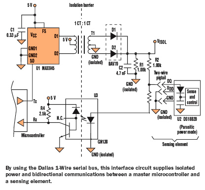
Medical and industrial applications often require galvanic isolation of 2500 V AC or higher for the safety of patients and equipment operators. The isolation barrier conveys not only power to the sensing element but also data to or from...
Replacing the LC modulation circuit with an active filter allows for the elimination of large and costly inductance coils in frequency shift key control demodulators. This approach not only reduces the size of the circuit but also enhances the...

The CA3140 is a 4.5 MHz BiMOS operational amplifier featuring MOSFET inputs and a bipolar output. This operational amplifier integrates the benefits of PMOS transistors and high voltage performance. The CA3140 operational amplifier is designed to provide high-speed performance while...
A micro power supply unit (PSU) is designed to power a breadboard with a voltage output of 5 volts. It can be connected to a 9V battery, a 12V source, or any other direct current (DC) power supply ranging...