
One-Wire Serial Bus Carries Isolated Power And Data

In this design, the galvanic isolation is achieved through the use of an optocoupler and an isolated transformer, ensuring that high voltage levels do not affect the low-voltage microcontroller. The circuit operates with a nominal switching frequency of 860 kHz, allowing for efficient data transfer and power management. The half-bridge rectification implemented by diodes D1 and D2 ensures that the output from the transformer is properly converted to a usable DC voltage.
The choice of components, such as the specific values for resistors and capacitors, is critical for maintaining the integrity of the data signals while ensuring that the power levels remain within operational thresholds for both the 1-Wire device and the microcontroller. The design emphasizes a compact layout, which is essential for applications with space constraints, such as in medical devices.
The isolation provided by this circuit not only protects sensitive components but also enhances the reliability of data transmission in environments where electrical noise or high voltages may be present. This makes the circuit suitable for a wide range of applications, from medical devices monitoring patient conditions to industrial sensors tracking environmental parameters. The ability to use a single data line for communication, along with power transfer capabilities, further simplifies the design and reduces overall costs, making it an attractive solution for engineers working in these fields.Medical and industrial applications often require galvanic isolation of 2500 V ac or higher for the safety of patients and equipment operators. The isolation barrier conveys not only power to the sensing element, but also data to or from that element.
Each data signal crossing the barrier-requires isolation. Consequently, designers can typically s ave costs in these applications by choosing a serial bus rather than a parallel bus. Serial buses include SPI, I2C, and the Dallas 1-Wire bus. The Dallas 1-Wire requires only one data line (plus ground) for bidirectional-communications. Because optoisolators are unidirectional devices, typical 1-Wire applications require two optos ”one for each direction of data flow. (SPI and I2C applications require a minimum of three optos. ) The 1-Wire bus not only allows bidirectional data flow, it also can transfer power in its "parasitic power mode.
" An isolated converter supplies power for the sensing element. Thus, most 1-Wire designs require two optos for the data interface: one opto for feedback to the isolated power supply, and a transformer for power-supply isolation. The circuit shown in the figure, implemented with an isolated transformer driver (U1) and a single optocoupler (U3), minimizes the component count required for isolation while maintaining a two-wire pigtail design (data plus ground to the 1-Wire sensing element).
U1 provides isolated and pseudoregulated power, and it enables the master to transmit data to the 1-Wire device across an isolated interface. The single opto`s location in the receive datapath lets the master receive isolated data from the 1-Wire device.
Note the following observations: U1 and transformer T1 generate approximately 4. 0 V at the VISOL node (upper right corner of the schematic). D1 and D2 implement a half-bridge rectifier for the transformer secondary. The connection between FS and VCC on U1 causes that device to switch at a nominal 860 kHz. Capacitor C2 filters the output and maintains the output level between positive cycles. R1 is included to discharge capacitor C2. The master microcontroller transfers data to the 1-Wire device by modulating U1`s SD pin on and off. When data isn`t being transferred, U1 is normally on and supplying power to the 1-Wire device, representing a logic high to the 1-Wire device. The VISOL node is approximately 4. 0 V at that time. To initiate communication, the master asserts a Reset Pulse by forcing SD high, turning off U1. With U1 off, the voltage at VISOL drops to the logiclow level of the 1-Wire device. Select R1, R2, R3, and C2 to permit VISOL to fall below the logic-low threshold (0. 8 V) in less than 5 µs or so. (R1 = R2 = 1. 00 k ©, R3 = 2. 00 k ©, and C2 = 4. 7 nF will yield a starting point for testing. But final values depend on the opto selected. ) While U1 is active, these four values must not allow VISOL to dip below the logic-high threshold of the 1-Wire device (2.
4 V). For the master to receive data from the 1-Wire device, the opto (U3) is modulated by the level of VISOL or the data pin of the 1-Wire device (DQ). When U1 is ON, the LED in U3 is ON. This forces Rx low. When the 1-Wire device pulls DQ low, the LED turns off and Rx goes high. Rx also goes high when U1 turns off, causing VISOL to drop and turn off the LED. (Tx and Rx logic for the microcontroller is the inverse of that for the 1-Wire device. ) So one opto, a transformer, and a Dallas 1-Wire serial link form an isolated sensor interface between a master microcontroller and a precision 1-Wire thermometer.
By keeping wiring and component costs to a minimum, the circuit supports highvolume medical and industrial applications. 🔗 External reference
Related Circuits

The TS2418 is a monolithic integrated circuit telephone tone ringer that utilizes a bridge diode. When paired with an appropriate transducer, it serves as a replacement for traditional electromechanical bells. This device is compatible with either a piezo transducer...
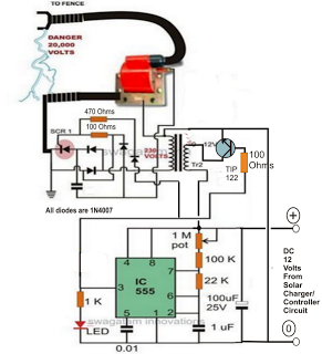
A fence charger or energizer is a device used to electrify a fence or boundary to protect the premises from human or animal intrusions. These boundaries are often located in large fields and parks, typically away from urban areas,...
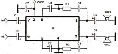
This series utilizes the TDA2822M integrated circuit (IC) as the primary amplifier. Additionally, alternative ICs such as KA2209, NJM2073, U2822B, and U2823B can be employed alongside the TDA2822M. The output power is limited to a maximum of 4 watts,...
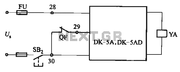
The DK-5A and DK-5AD AC power control circuit is illustrated in Figure 6-77. The figure includes a closing button (SBz) and a line (YA) connected to the closing electromagnet coil (U). This circuit is designed for the operation of...

RS-232 Serial Interface Status Indicator Circuit. This circuit utilizes a single logic integrated circuit (IC) to indicate the transmission (TXD) and reception (RXD) statuses of a serial interface. The RS-232 Serial Interface Status Indicator Circuit is designed to provide visual...

This circuit is essentially a crystal radio equipped with an audio amplifier that demonstrates considerable sensitivity, successfully receiving multiple strong stations in the Los Angeles area using a minimal 15-foot antenna. Employing a longer antenna can enhance signal strength;...