
Isolated Power Supply Is Suitable For Telecom/Datacom Applications
The 50W isolated forward-converter switching supply is engineered to meet the specific demands of telecom applications, where reliability and efficiency are paramount. This design employs a forward converter topology, which is known for its ability to provide electrical isolation between the input and output, enhancing safety and reducing noise interference.
Key components of the circuit include a high-frequency switching transistor, typically a MOSFET, which controls the energy transfer from the input to the output through a transformer. The transformer not only provides isolation but also steps down the voltage to the desired output level. The design incorporates feedback mechanisms to regulate the output voltage, ensuring stability under varying load conditions.
The power supply operates by converting the input DC voltage to high-frequency AC using the switching transistor. The AC voltage is then coupled through the transformer to the rectifying stage, where it is converted back to DC. This process is often complemented by filtering capacitors to smooth the output and reduce ripple voltage.
Thermal management is also a critical aspect of the design, as the switching components can generate significant heat during operation. Adequate heat sinking and possibly active cooling solutions may be implemented to maintain optimal operating temperatures and ensure long-term reliability.
Overall, this 50W isolated forward-converter switching supply represents a robust solution for telecom applications, combining efficiency, safety, and performance in a compact design.A 50W isolated forward-converter switching supply for telecom applications is described. Most aspects of the design are discussed.. 🔗 External reference
Related Circuits
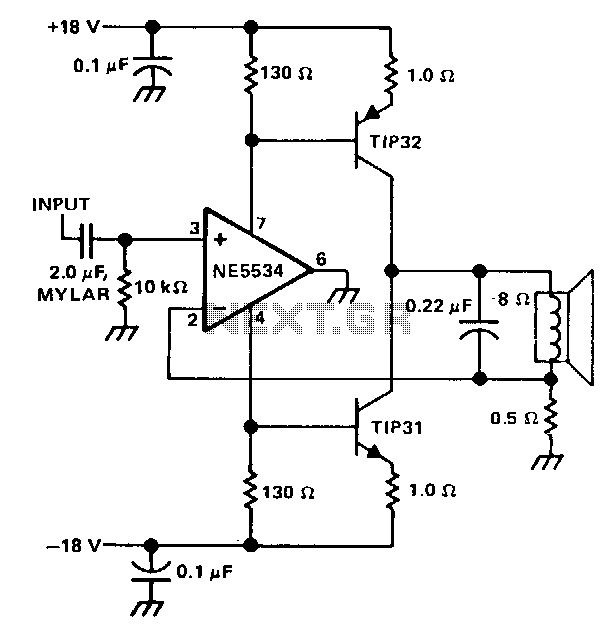
The single speaker amplifier circuit utilizes current feedback instead of the more commonly used voltage feedback. The feedback loop originates from the junction of the speaker terminal and a 0.5-ohm resistor, connecting to the inverting input of the NE5534...
A DC-DC power supply schematic is required that outputs a voltage between 12.7V and 14.5VDC, with an input voltage range from 12VDC upwards. The design of a DC-DC power supply capable of outputting a regulated voltage between 12.7V and 14.5VDC...
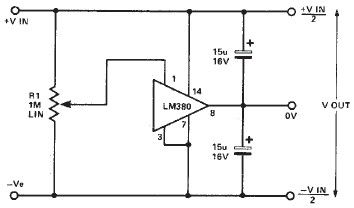
A simple split power supply circuit can be designed using the schematic diagram based on the LM380 audio power integrated circuit (IC). The output voltage regulation is dependent on the circuit feeding the LM380. The power dissipation is approximately...
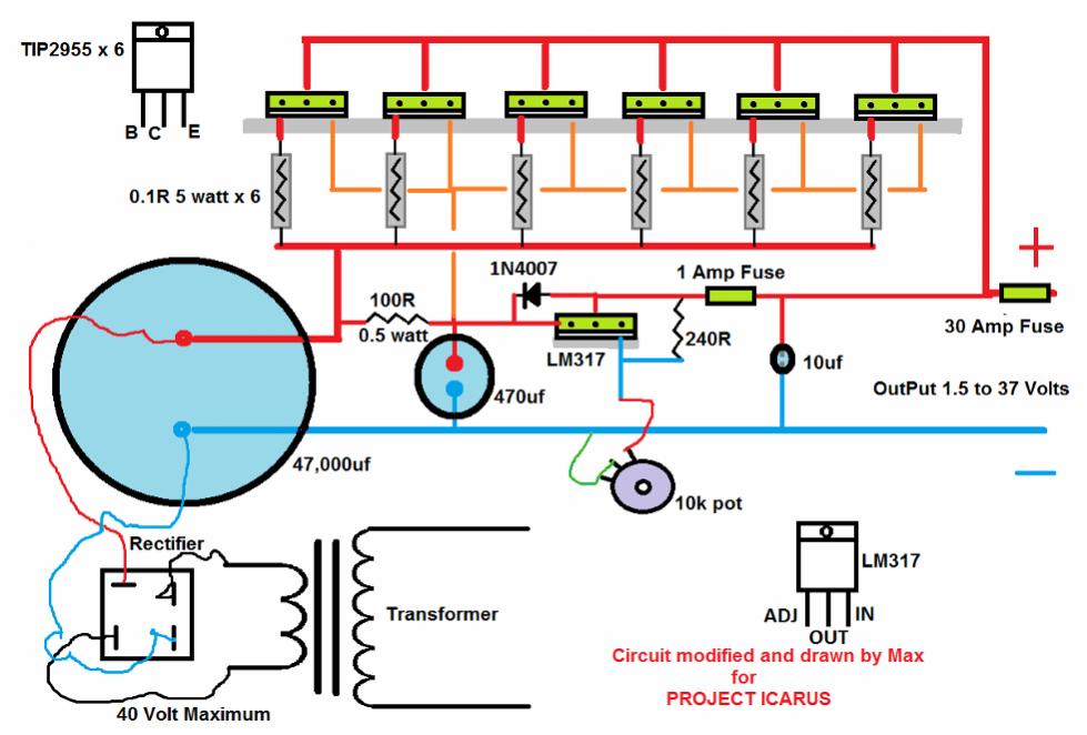
This chapter contains circuit diagrams for several power supplies designed for pulsed solid-state lasers. These include units suitable for driving the widely used Hughes ruby and YAG rangefinder laser assemblies, one utilizing the flash from a disposable pocket camera,...
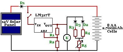
The circuit is designed to power a CCTV camera, provide lighting inside a nestbox, and charge batteries using a photovoltaic (PV) solar panel. It includes a circuit diagram for a solar-powered wireless CCTV camera with battery backup. D1 is...
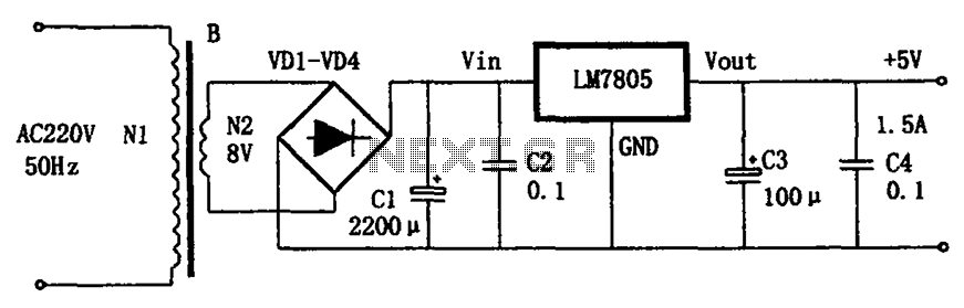
The circuit illustrated in the figure provides an output voltage of +5V and an output current of 1.5A. It comprises a power transformer, a bridge rectifier circuit consisting of diodes D1 to D4, and filter capacitor C1. Additionally, capacitors...