
Data-Logger Shield for Arduino
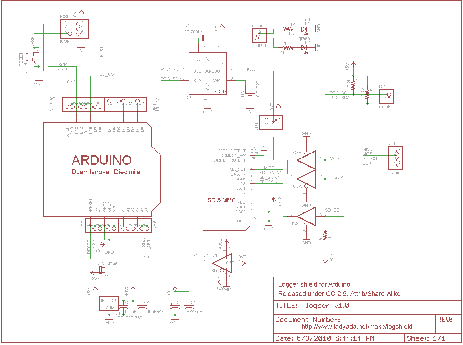
The power supply circuit is designed to provide a reliable 3.3V output capable of delivering up to 250mA. This is crucial for applications requiring higher current, such as when interfacing with SD cards during write operations. The stability of the output is ensured by the inclusion of bypass capacitors that filter out noise across a range of frequencies, thereby enhancing the performance of both the 5V and 3.3V lines.
The DS1307 real-time clock chip is integrated into the design, featuring a CR1220 battery backup that maintains timekeeping even during power outages. Communication with the Arduino is achieved through the I2C interface, which requires careful attention to the pull-up resistor values to ensure proper signal integrity. The choice of 2.2kΩ resistors for the SCL and SDA lines is standard, but flexibility is provided for alternative resistor values based on availability.
The SD card interface utilizes a buffer IC3 that serves as a level shifter, converting the 5V logic levels from the Arduino to 3.3V levels suitable for the SD card. This is a critical safety measure to prevent damage to the card, as applying 5V directly to a 3.3V device can result in permanent failure. The circuit design also incorporates a pull-up resistor on the chip select (CS) line, preventing accidental data corruption during programming operations when an SD card is present.
The data logger shield's pin configuration allows for efficient communication with both the real-time clock and SD card. The use of analog pins 4 and 5 for I2C communication is standard practice, while the SD card's digital pins are carefully chosen to ensure compatibility with the Arduino's SPI interface. The ability to modify pin assignments for pin 10 provides additional flexibility for developers, although it is essential to remember the requirement for pin 10 to remain an output for proper functionality.
Overall, this design presents a well-thought-out approach to integrating power management, real-time clock functionality, and SD card communication within an Arduino platform, ensuring robust performance for data logging applications.There is a small power supply on the board for generating 3. 3V @ 250mA. We don`t use the `built in` 3. 3v regulator on the Arduino because its only guaranteed up to 50mA and some SD card need a lot of power when writing. This supply is nice and steady, we can use it as an analog reference too! We have two sets of bypass caps to try and keep both 5V and 3. 3V supply nice and clean - the 100uF ones are for the low frequency noise and 0. 1 for higher frequency The real time clock is the DS1307 from Maxim, which has a battery backup (CR1220) and communicates with the Arduino via i2c (the SCL and SDA lines). i2c requires pullup resistors on the clock and data lines, which you see as R1 and R2. 2. 2K are good values, but if you`re in a bind, 1. 0K to 10K will probably work fine. The SD card holder is connected to the Arduino through a buffer IC3. The buffer is a level shifter, converting the 5V signals into 3. 3V ones which are safe to use. (For some cards its OK to use 5V signals but you risk the card being permanently damaged!) There is a pull up on the CS line so that if you program the Arduino with a ISP programmer while theres a card in, you wont scramble it.
There are two `unused` lines from the SD card - Card Detect is shorted to ground when a card is inserted. Write Protect is shorted to ground when a card with the safety switch flipped is inserted. Finally we have the arduino interface. The Datalogger shield uses 6 pins. Analog 4 and 5 are the i2c hardware pins. The SD card uses Digital pins 13, 12, 11, and 10. The first three are pretty much required. If you really need pin 10, you can edit the library header file and change it from pin 10 to any other pin.
BUT you must have pin 10 as an output, if its an input, the SD interface wont work (its a really annoying thing about AVRs - not sure why this is). A standard 6 pin ISP header is available in case you want to program the Arduino with code using a stand-alone programmer
🔗 External reference
Related Circuits
This section of code outlines the main sequence of operation for the sequencer. A for loop is utilized to determine which step the sequencer is operating in. Within this loop, an address is generated using the assignByteToPins() function, which...
After completing the prototype and ensuring the sketch functions correctly, it is time to construct the circuit. The aim is not to provide a detailed explanation of how to create printed circuit boards, but rather to offer a general...
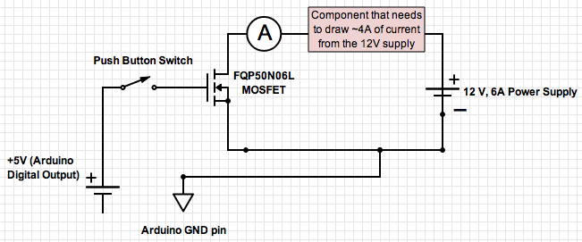
If the ground of the Arduino is disconnected from the negative terminal of the power supply, current flows through the MOSFET, even when the switch is not closed. In an electronic circuit involving an Arduino and a MOSFET, maintaining a...
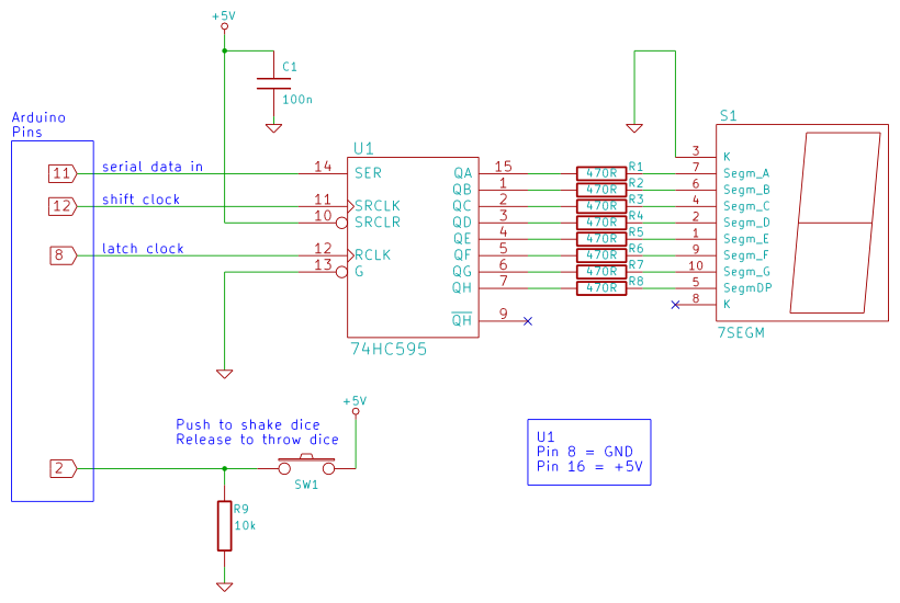
Arduino 7-segment display dice circuit and tutorial with Arduino sketch. Build a dice that is shaken by holding a button in and thrown by releasing the button. The shake, throw, and number thrown are animated and displayed on a...
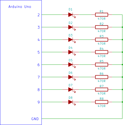
Construct a Knight Rider LED display on a breadboard using an Arduino controller. This is a straightforward circuit designed for beginners in electronics, utilizing an Arduino Uno. The Knight Rider LED display emulates the iconic light sequence from the television...
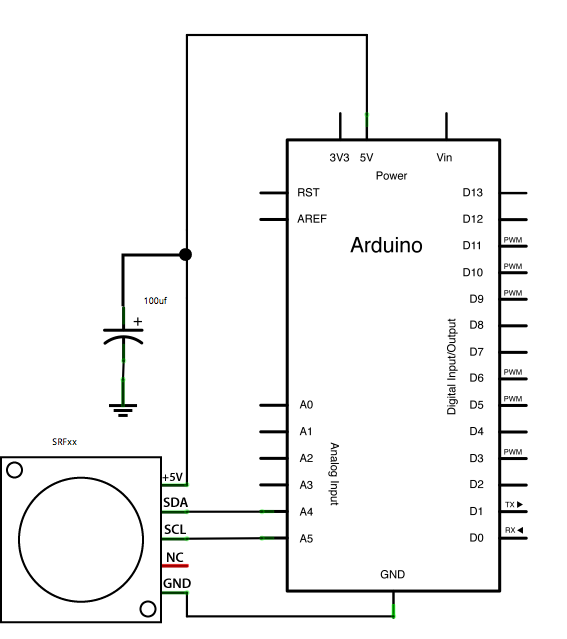
This example demonstrates how to read a Devantech SRFxx, an ultrasonic range finder that communicates via the I2C synchronous serial protocol, using Arduino's Wire Library. The I2C protocol utilizes two wires for data transmission: a serial clock pin (SCL)...