
dc control for triacs

The described circuit utilizes the MOC3041 optocoupler for controlling a power triac in mains voltage applications, particularly where rapid switching is essential. The optocoupler provides electrical isolation, which is crucial for safety and performance. The zero-crossing detection feature minimizes electromagnetic interference and enhances the reliability of the triac operation.
In designing this circuit, attention must be given to the selection of the AW-suffix triac, which is suitable for applications that demand higher rates of change in voltage and current, thus improving robustness against noise and ensuring efficient operation. The series gate resistor configuration is critical for handling the high voltages present in mains applications, and the specified spacing for solder pads ensures compliance with safety standards, particularly for Class II devices.
For optimal performance, the addition of a 220 nF capacitor at the input of the optocoupler aids in pulse shaping, allowing the circuit to respond effectively to brief input signals. This design consideration is particularly important in applications where signal integrity and timing are paramount, such as in audio systems where synchronization with light effects is required.
Overall, this circuit design demonstrates a comprehensive approach to safely and effectively controlling high-voltage loads using modern electronic components while adhering to safety and operational standards.If a circuit is to switch a mains voltage, a relay is a simple solution in cases where switching times are long and high currents are involved. However, at lower currents, and in particular where rapid switching is required, such as in sound-to-light systems, a relay no longer ¬lls the bill.
Electrical isolation is often a requirement, which rules out driving a triac via a transistor. Here we use the MOC3041 optocoupler, which is specially designed for such applications, to drive a power triac. The control circuit therefore remains galvanically isolated from the mains. The internals of the optocoupler are somewhat more complex than appears from the circuit diagram. A special zero-crossing detector circuit in the optocoupler ensures that the connected triac is only triggered when the alternating mains voltage goes through zero.
This has the advantage of generating less interference compared to switching the triac at arbitrary phase in a cycle. Indeed, it means that we can dispense with the suppressor choke at the output that would otherwise be necessary.
If very brief pulses are likely to be present at the input to the opto-coupler, a 220 nF capacitor should be connected between the input of the circuit and the emitter of T1 to lengthen the drive pulses. This ensures that the triac will be triggered even with very short input pulses, which might otherwise miss the zero-crossing point of the mains waveform.
The triac should be an AW-suffix type. These types are less sensitive, but have higher dv/dt and di/dt specifications. The gate resistance must be constructed from two resistors connected in series, since normal resistors are not suitable for direct use with mains voltages. It is also necessary to exercise care around the opto-coupler. In order to guarantee Class II isolation the solder pads on the input and output sides must be separated by at least 6 mm.
The leads may therefore need to be bent outwards when soldering. 🔗 External reference
Related Circuits
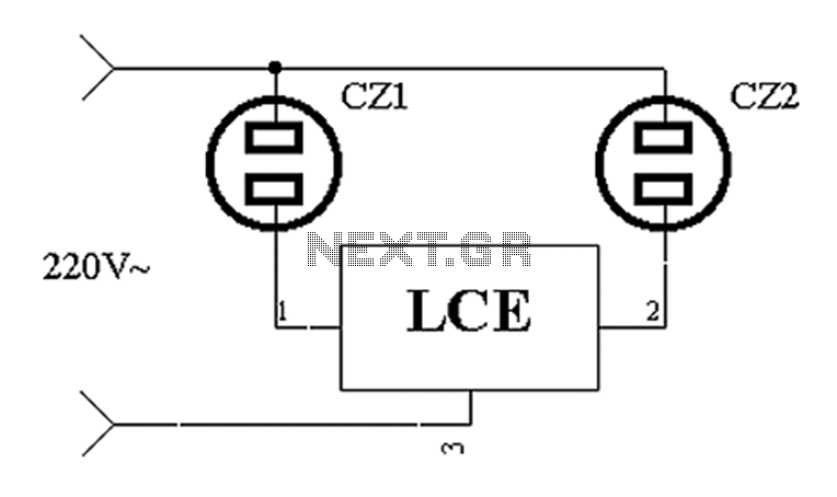
The application circuit operates the device as illustrated below. It is designed for cooling electrical equipment, typically utilizing a cooling fan to dissipate heat. The LCE employs a synchronous control socket on the device and its connections remain unchanged....

This project has been on the agenda for some time. The primary concern is that the winch on the Jeep is permanently connected to the battery, allowing unauthorized individuals in parking lots to potentially misuse the winch remote. To...
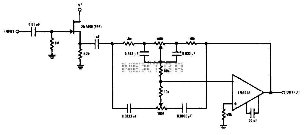
The 2N5458 JFET offers high input impedance and low noise characteristics, making it suitable for buffering an operational amplifier feedback tone control circuit. The 2N5458 is a Junction Field Effect Transistor (JFET) known for its superior electrical characteristics, particularly in...
The simplest of all motor controllers (besides a straight on/off switch) is the contactor controller. I designed this contactor controller for use in my electric scooter project. It is based around three 12V relays, two 12V batteries, two switches...

The QAMI5516 is an integrated demodulator and decoder solution designed for digital cable receivers, capable of handling compressed video, audio, and data services. This QAM demodulator executes intermediate frequency (IF) to MPEG-2 block processing of QAM carriers. The resulting...

The LM4610 utilizes a DC signal to manage the tone (bass/treble), volume, and balance circuits. The benefits of employing DC control include the ability to operate in mono mode. The LM4610 is an integrated circuit designed for audio applications, specifically...