
DC 2 speed Motor Controller
Notes
S1 closes K3 and thus causes M1 to operate. S2 activates K1 and K2, reconfiguring the batteries for series operation and thus causes M1 to operate at "fast" speed. B1 and B2 should be chosen based on the current requirements of M1. Often, sealed lead-acid type batteries are available at local suppliers for surprisingly low prices. These batteries are ideal for things such as scooters, go-karts, etc. The relays are standard automotive type relays, available cheaply from any auto parts store. Your motor will depend on your requirements. 12V motors will normally run fine at 24V, and vice versa. You will notice that in series mode, all three relays only pull power from B2. This is because the relays have 12V coils, and it is impossible to switch the batteries from series to parallel and keep power to the coils at the same time. This does, however, mean that B2 is discharged slightly before B1. This should normally not be an issue unless the batteries are being drained completely "dead". Draining a battery dead is not good for it in any situation and should be avoided. If you wish, you can use a small 12V battery to run the relays separately. You can add two more speeds to this controller using the schematic below. It connects at points A and B shown above on the controller schematic. K1 is simply another of the same relay as used in the controller. S1 is another switch. R1 needs to be chosen based on your motor, but it will be of low value (under 10 Ohm) and high wattage (normally at least 100W). It must be capable of handling the full current drawn by the motor. This is not exactly an efficient way to limit current to the motor as excess current is dissipated as heat by the resistor, so it is normally only used for a "starter" speed.
The contactor motor controller is a straightforward yet effective design for controlling the speed of a DC motor, particularly in applications such as electric scooters. The circuit utilizes three 12V relays (K1, K2, K3), two 12V batteries (B1, B2), and two switches (S1, S2) to manage the power supply to the motor (M1).
In the idle state, both batteries are connected in parallel, allowing for easy recharging and ensuring that the voltage remains stable at 12V. When S1 is activated, K3 closes, providing power to the motor and initiating operation at a slow speed. For higher speeds, S2 is engaged, which activates relays K1 and K2 to reconfigure the battery connections into a series configuration. This arrangement increases the voltage supplied to the motor, thus allowing it to operate at a faster speed.
The selection of batteries (B1 and B2) is critical and should be based on the current rating of the motor (M1). Sealed lead-acid batteries are often recommended due to their availability and cost-effectiveness. The relays used in this controller are standard automotive relays rated for 30A, which are suitable for handling the motor's current requirements.
It is important to note that in series mode, only battery B2 supplies power to the relays. This design choice is made to simplify the switching mechanism, though it does lead to a slight imbalance in battery discharge rates. To mitigate potential issues from discharging one battery more than the other, it is advisable to avoid completely draining either battery, as this can lead to reduced battery lifespan.
For users seeking additional speed settings, the circuit can be modified by integrating additional components at designated points in the schematic. This includes adding another relay (K1) and switch (S1) along with a current-limiting resistor (R1), which should be selected based on the motor's specifications. The resistor should be of low resistance (under 10 Ohm) and high wattage to handle the motor's current without overheating.
Overall, this contactor controller design offers a reliable and straightforward solution for controlling motor speed in electric vehicles, with the flexibility to accommodate various battery and motor configurations.The simplest of all motor controllers (besides a straight on/off switch) is the contactor controller. I designed this contactor controller for use in my electric scooter project. It is based around three 12V relays, two 12V batteries, two switches and of course a motor. Having no silicon to "fry", it is quite reliable and robust. A contactor controller works by rearranging the two (or more) supply batteries between series and parallel.
This gives the motor a slow speed (batteries in parallel, current adds) and a fast speed (batteries in series, voltage adds). This assures that both batteries are discharged equally. When the circuit is "at rest", the batteries are connected in parallel, which allows easy recharging.
K1, K2, K3 3 12V 30A SPDT Relay (See Notes) S1, S2 2 SPST Switch or Button B1, B2 2 12V Battery (See Notes) M1 1 12V or 24V Motor (See Notes) MISC 1 Case, Wire, etc. Notes S1 closes K3 and thus causes M1 to operate. S2 activates K1 and K2, reconfiguring the batteries for series operation and thus causes M1 to operate at "fast" speed.
B1 and B2 should be chosen based on the current requirements of M1. Often, sealed lead-acid type batteries are available at local suppliers for surprisingly low prices. These batteries are ideal for things such as scooters, go-karts, etc. The relays are standard automotive type relays, available cheaply from any auto parts store. Your motor will depend on your requirements. 12V motors will normally run fine at 24V, and vice versa. You will notice that in series mode, all three relays only pull power from B2. This is because the relays have 12V coils, and it is impossible to switch the batteries from series to parallel and keep power to the coils at the same time. This does, however, mean that B2 is discharged slighty before B1. This should normally not be an issue unless the batteries are being drained completely "dead". Draining a battery dead is not good for it in any situation, and should be avoided. If you wish, you can use a small 12V battery to run the relays separately. You can add two more speeds to this controller using the schematic below. It connects at points A and B shown above on the controller schematic. K1 is simply another of the same relay as used in the controller. S1 is another switch. R1 needs to be chosen based on your motor, but it will be of low value (under 10 Ohm) and high wattage (normally at least 100W).
It must be capable of handling the full current drawn by the motor. This is not exactly an efficient way to limit current to the motor as excess current is dissipated as heat by the resistor, so it is normally only used for a "starter" speed. 🔗 External reference
Related Circuits
Stepper motors consist of a permanent magnet rotating shaft, known as the rotor, and electromagnets on the stationary part that surrounds the motor, referred to as the stator. One complete rotation of a stepper motor is illustrated. At position...
This project automates home appliances via a Bluetooth-enabled PC. A USB Bluetooth adapter is utilized on the PC side, while a Serial Bluetooth module is employed for communication. This project involves the integration of a Bluetooth-enabled PC with home appliances...
How can graphical LCDs be controlled using a microcontroller? Is there any datasheet available? Graphical LCDs (Liquid Crystal Displays) are widely used in various electronic applications for displaying complex graphics and text. To control these displays with a microcontroller, several...
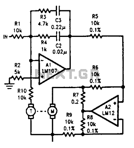
The tachometer, mounted on the same shaft as the DC motor, functions as a generator, producing a DC output voltage that is proportional to the motor's speed. A summing amplifier, labeled as Al, manages its output to ensure that...
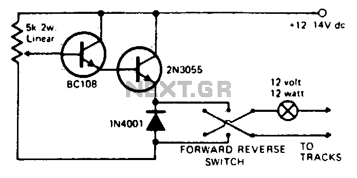
Any NPN small signal transistor can replace the BC 108 shown in the circuit. Similarly, any appropriate NPN power transistor can substitute for the 2N3055. It is essential to mount the output transistor on a suitable heat sink. Short...
A PIR sensor is triggered when using a timer to wait for 2 seconds after the sensor is activated. Without the timer, the sensor operates as intended. The PIR sensor is connected to an ATMega328p microcontroller, which has three...