
EPROM adapter for ATMEL 89 Series Flash Microcontroller Programmer Ver 2.0

In this circuit, diode D1 serves a critical role in ensuring that the voltage supply (VDD) is isolated when programming the 24-pin devices. This isolation is essential to prevent potential backfeeding of voltage that could damage the programming interface or the devices themselves. The resistor R1 is used in conjunction with the diode to limit the current flowing through the circuit, providing an additional layer of protection and stability during the programming process.
The jumper J3 is a key component that allows for flexibility in device programming. When the jumper is shorted, it creates a closed circuit that enables the programming of 24-pin devices. Conversely, when the jumper is open, it disconnects the circuit, allowing for the programming of 28-pin devices without interference from the 24-pin configuration. This design feature enhances the versatility of the programming environment, accommodating different device types without requiring significant modifications to the circuit.
The EEPROMs mentioned are designed to be pin compatible with their EPROM counterparts, making it easier to replace or upgrade devices without redesigning the entire circuit. This compatibility ensures that the same PCB layout can be utilized for both types of memory, streamlining manufacturing and reducing costs. The careful arrangement of components and the use of isolation techniques contribute to a reliable and efficient programming circuit suitable for a variety of applications in electronic design.Diode D1 and resistor R1 provide the VDD isolation when programming the 24 pin devices. The jumper J3 must be shorted for 24 pin devices, and open circuit for 28 pin device programming. Following EEPROMs are pin compatible with their EPROMs version, 🔗 External reference
Related Circuits
The circuit was designed to obtain signals through amplitude modulation, exhibiting good sensitivity and selectivity. Amplitude modulation. The amplitude modulation (AM) circuit is engineered to effectively capture and process radio frequency signals. The design focuses on achieving high sensitivity, allowing...

The LT1618 not only provides an accurate input current limit but also functions as a regulated output current source suitable for current-source applications. One such application is driving white LEDs, for which the LT1618 is particularly well-suited. It operates...

The 2N4416 JFET offers noise figures below 3 dB and a power gain exceeding 20 dB. Its exceptional low crossmodulation and low intermodulation distortion make it an ideal choice for an input stage. The output connects to an LM171,...
A slice of the SM2965 includes a canonical 80C32 microcontroller, FLASH memory, E2PROM (28SF512), SRAM for static data storage, and a watchdog timer (WDT). The cost performance of the SM2965 is notably high. This device is designed as a...
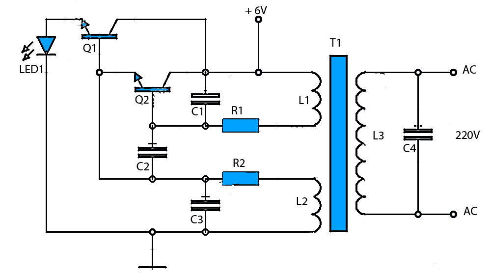
6V to 220V Inverter Schematic. Starting from a 6-Volt input on the DC current to produce a 220-Volt AC output. The inverter circuit converts a low voltage DC input, specifically 6 volts, into a high voltage AC output of 220...

These novel relay driver circuits have the capability to activate a relay with a coil voltage rating that is double the supply voltage (Vcc). Once the relay is activated, the armature is maintained using Vcc, resulting in a significant...