
digitally controlled oscillator dco design
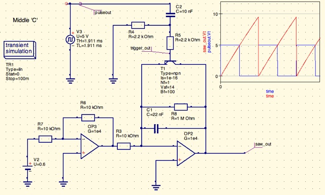
The circuit described involves an integrator configuration using two operational amplifiers (op-amps) to create a control voltage from a PWM signal generated by an Arduino microcontroller. The PWM signal is filtered to produce a smooth control voltage that drives the integrator circuit. The output of the integrator is a ramp voltage, which is then converted into a sawtooth waveform by using a transistor to short the ramp voltage to ground at the desired frequency. This method effectively generates a sawtooth waveform, which is a common waveform used in synthesizers.
The design acknowledges that this configuration does not qualify as a true oscillator since it relies on external control from the microcontroller. The goal is to achieve a stable output without the frequency drift associated with traditional voltage-controlled oscillators, which can be affected by temperature variations. By utilizing PWM to charge a capacitor through a resistor, the circuit can maintain a consistent ramp peak, although the ramp's linearity may vary with frequency.
In terms of component selection, the choice of op-amps is critical. The designer considers using a JFET op-amp like the TL081, which offers better performance characteristics, including lower noise and improved slew rates compared to the LM324N. The op-amp's specifications must be evaluated to ensure compatibility with the circuit's requirements, particularly regarding the PWM frequency and the acceptable level of ripple on the control voltage.
Additionally, the circuit may employ AC coupling techniques to mitigate the limitations of single-supply op-amps, which typically cannot output voltages close to ground. By AC coupling the output, the designer can avoid issues related to the op-amp's inability to reach 0V, thus improving the overall performance of the sawtooth generator.
Considering a dual power supply of ±15V simplifies the design by allowing the op-amps to operate within a wider voltage range, thereby enhancing their linearity and performance. This choice also provides more headroom for the output signals, reducing distortion and improving the quality of the generated waveforms. Overall, the proposed circuit aims to achieve a reliable and high-quality sawtooth waveform suitable for use in a music synthesizer application.I am trying to design a digitally controlled analogue oscillator. The idea is that a control voltage is generated by the a microcontroller (Arduino) which is used via the 2 op amps, resistor and capacitor network which forms a integrator circuit. The microcontroller will also send out a squarewave (top left) at the desired frequency which gets con
verted eventually via the transistor and shorts the ramp voltage to ground. This forms the sawtooth circuit. That`s technically not an oscillator, it`s a sawtooth generator. An oscillator is autonomous (no external input), and free-runs by virtue of positive feedback. You don`t need the 1Meg resistor. It just makes your ramp slightly nonlinear. You will have to adjust your values slightly if you want to omit it and still get exactly 9. 5V peak. Yes, it`s not a true oscillator. I`m trying to design a digital oscillator for a music synthesizer. The outputs will eventually be ramp (sawtooth) and squarewave. I did not want to go down the stand voltage controlled oscillator because of frequency drifting due to temperature changes etc. I`m going to get the microprocessor to send out a PWM and then filter it to create a control voltage.
I`ve simulated that by the battery you see in the bottom left (0. 6v). You can see the output control values i`ve calculated in the spreadsheet. Are you going to AC-couple the output of your sawtooth generator The reason I ask is that a single-supply op amp, even with rail-to-rail output, can only get within ‰ 100mV of zero volts. If you AC-couple, I suppose that won`t matter. I can show you how to do it with a single supply, but if I post the schematic, On1aag will come up with something with half as many parts, and compare me to Rube Goldberg again.
I can show you how to do it with a single supply, but if I post the schematic, On1aag will come up with something with half as many parts, and compare me to Rube Goldberg again. What kind of single-supply, rail-to-rail I/O op amps do you have I would like to look at the specs, and maybe run some simulations before I post a circuit that will disappoint you if your op amp is not up to the task.
Are you going to AC-couple the output of your sawtooth generator The reason I ask is that a single-supply op amp, even with rail-to-rail output, can only get within ‰ 100mV of zero volts. If you AC-couple, I suppose that won`t matter. I can show you how to do it with a single supply, but if I post the schematic, On1aag will come up with something with half as many parts, and compare me to Rube Goldberg again.
What kind of single-supply, rail-to-rail I/O op amps do you have I would like to look at the specs, and maybe run some simulations before I post a circuit that will disappoint you if your op amp is not up to the task. what you can do is to use the pwm to charge a cap through a resistor and discharge once it gets to a particular voltage.
the ramp would not be perfect and the frequency would be value dependent but the ramp peak (volume) would be fixed instead of varying with frequency. Well, It`s not a very good op amp, but the attached circuit works in simulation. Due to the finite slew time when the ramp resets, doubling the amplitude control voltage with each doubling of frequency will not quite keep the amplitude constant.
You may have to use a lookup table for the PWM duty cycle. A faster slewing op amp would allow you to use a shorter reset pulse (lower value for C2), which would reduce but not eliminate the slewing problem. U1a can double as the op amp in a 2 or 3 pole lowpass filter for your PWM if you need it. Let us know if you want to do that. We will need to know the PWM frequency, and how much residual ripple you can tolerate on the control voltage.
what you can do is to use the pwm to charge a cap through a resistor and discharge once it gets to a particular voltage. the ramp would not be perfect and the frequency would be value dependent but the ramp peak (volume) would be fixed instead of varying with frequency.
Well, It`s not a very good op amp, but the attached circuit works in simulation. Due to the finite slew time when the ramp resets, doubling the amplitude control voltage with each doubling of frequency will not quite keep the amplitude constant. You may have to use a lookup table for the PWM duty cycle. A faster slewing op amp would allow you to use a shorter reset pulse (lower value for C2), which would reduce but not eliminate the slewing problem.
U1a can double as the op amp in a 2 or 3 pole lowpass filter for your PWM if you need it. Let us know if you want to do that. We will need to know the PWM frequency, and how much residual ripple you can tolerate on the control voltage. Roff. Thank you very much for taking the time to look at this. I`ve took your feedback about the slew issues on the LM324N. So would a jfet opamp like the TL081 be a better choice. Also. I`ve decided that I`m going to have to go down the positive and negative supply route. Probably will supply with +/- 15v. Is that a better choice. Does that simplify the circuit. 🔗 External reference
Related Circuits
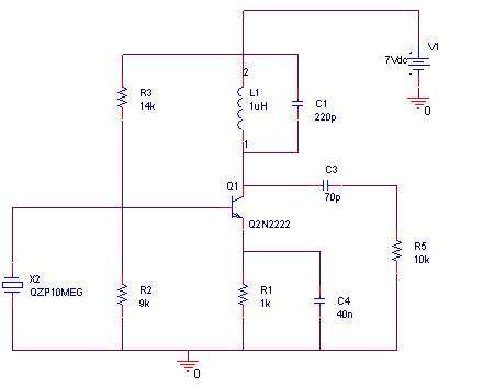
A simulation of a 27 MHz transmitter circuit is to be conducted using PSPICE. The circuit diagram is provided as Figure 1 in the following content. The 27 MHz transmitter circuit typically consists of several key components, including an oscillator,...
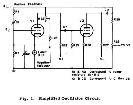
After repairing several Hewlett Packard vacuum tube voltmeters, research was conducted on the company's history. An HP-200C oscillator was located, which closely resembles the company's initial product. It is a Wien bridge resistance-tuned oscillator featuring a light bulb stabilized...
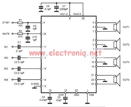
The input capacitor is used for low-frequency cut-off, with a standard value of 0.1 µF, resulting in a cut-off frequency of approximately 16 Hz. The input capacitor plays a crucial role in filtering unwanted low-frequency signals in electronic circuits. By...
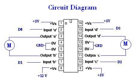
A remote Sun SPOT will transmit data to a Sun SPOT mounted on a car, which will control an integrated circuit (IC) according to the digital input/output pins D0 to D3. The IC will subsequently drive the motors that...
An exhaust fan is a crucial component in kitchens. This document presents a simple circuit designed to control kitchen fans by monitoring the ambient temperature. It is built around... The circuit for controlling an exhaust fan based on ambient temperature...
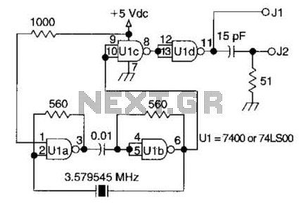
A circuit utilizing one 7400 TTL can operate with fundamental type crystals ranging from 1 to approximately 13 MHz. The output is rich in harmonics, making this oscillator suitable for calibration and testing applications. The circuit in question employs a...