
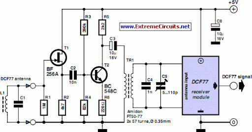
DCF77 Preamplifier
The radio-controlled clock project leverages a microcontroller to receive time signals transmitted from a time signal transmitter, typically operated by a national timekeeping authority. The core components of this project include a microcontroller unit (MCU), a radio receiver module, a display (such as an LCD or LED), and a power supply.
The microcontroller serves as the central processing unit, interpreting the signals received from the radio receiver. The receiver module is designed to pick up specific frequencies, often in the range of 60 kHz, which are used for time synchronization. The pre-adjusted ferrite antenna enhances the sensitivity and selectivity of the receiver, allowing it to effectively capture weak signals.
The display component is responsible for presenting the time information to the user. It can be configured to show hours, minutes, and seconds, along with additional features such as date or temperature, depending on the complexity of the design.
Power supply can be provided through batteries or a direct connection to a power source, ensuring the clock remains operational without interruption. The circuit design typically incorporates a voltage regulator to maintain stable operation under varying load conditions.
Overall, this project exemplifies the integration of microcontroller technology with radio frequency communication, resulting in an accurate and reliable timekeeping device suitable for a variety of applications.A popular project among microcontroller aficionados is to build a radio-controlled clock. Tiny receiver boards are available, with a pre-adjusted ferrite.. 🔗 External reference
Related Circuits
The electronic switch functions as a multifunctional preamplifier. It features a five-way touch electronic switch, a high-speed DC servo RIAA ultralow distortion amplifier, and can control volume, tone, and power amplifier electrical path phase. The TC9152, shown in Figure...
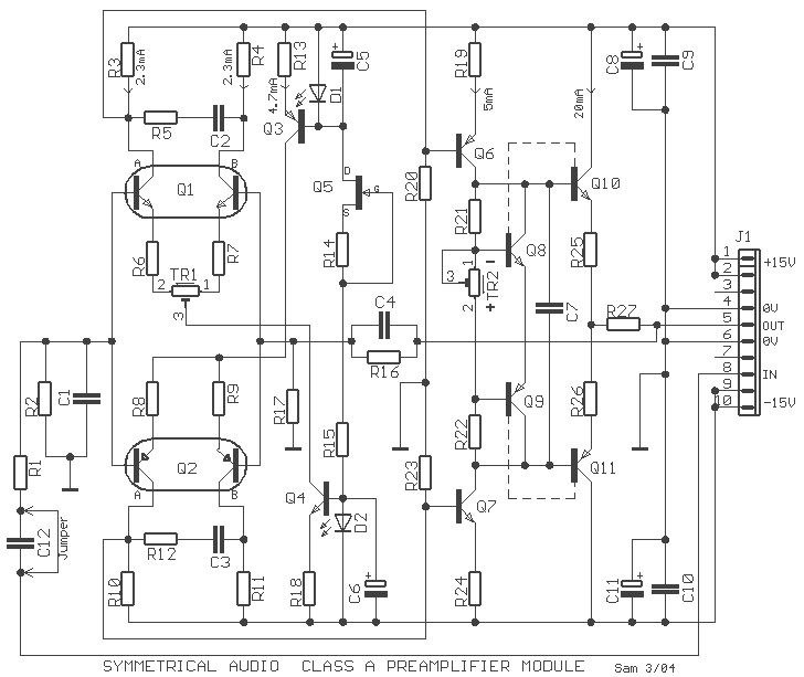
The preamplifier that appears in the figure is a completely symmetrical preamplifier, from the input as the exit and it works in Class A. It does not have somebody innovation, simply it uses good solutions, in order the result...
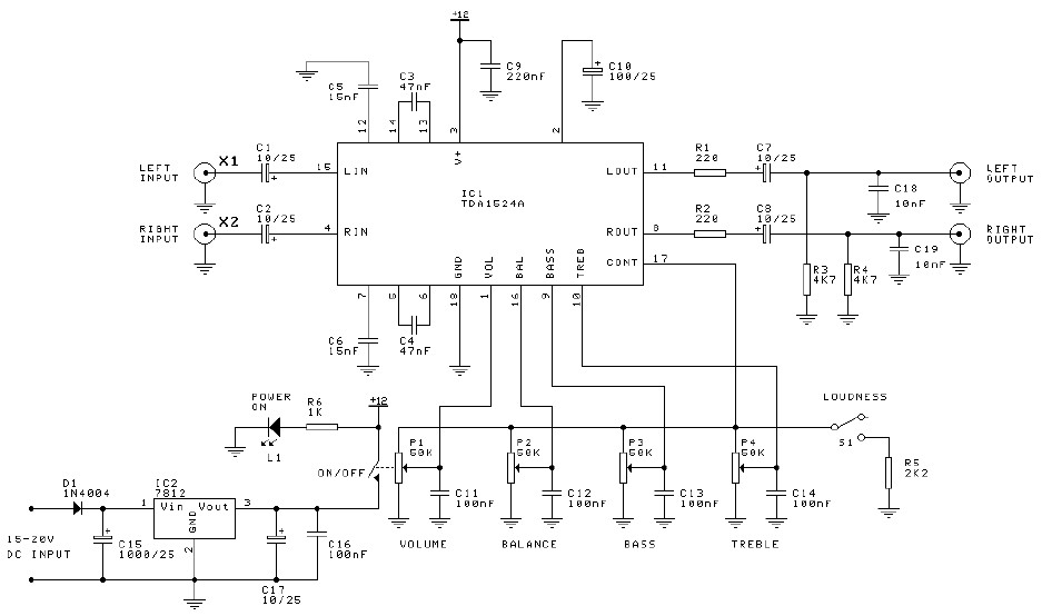
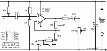
Preamplifier and tone control circuit based on the TDA1524A. The tone control circuit module is included in this preamplifier circuit, allowing for direct connection of the output channels to a stereo power audio amplifier circuit. This RIAA stereo preamplifier...
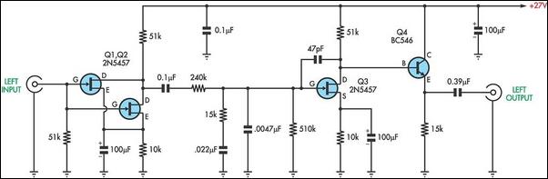
There are two types of preamplifiers for magnetic phono cartridges. The most common type includes an RIAA equalization network in the feedback loop, as described in the March 2002 issue of SILICON CHIP. The second type, previously used in...
This is a simple stereo electret microphone preamplifier circuit. For optimal performance, it is recommended to use solid or film capacitors and metal film resistors. The circuit is based on a single IC, the LM358. It is straightforward, cost-effective,...
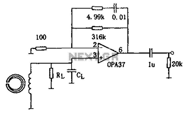
The circuit is a 90s common recorder head amplifier circuit that utilizes the ultra-low noise precision operational amplifier OPA37 as a preamplifier. This circuit is capable of providing standard NAB equalization. At a frequency of 1 kHz, it achieves...
Warning: include(partials/cookie-banner.php): Failed to open stream: Permission denied in /var/www/html/nextgr/view-circuit.php on line 713
Warning: include(): Failed opening 'partials/cookie-banner.php' for inclusion (include_path='.:/usr/share/php') in /var/www/html/nextgr/view-circuit.php on line 713