
passive riaa preamplifier
The described preamplifier circuit for magnetic phono cartridges is designed to effectively amplify low-level audio signals while maintaining fidelity and minimizing noise. The first stage utilizes two FETs (Q1 and Q2) in parallel, which helps to reduce noise through the averaging of any thermal noise generated by the individual FETs. This configuration is particularly advantageous in audio applications, where signal integrity is paramount.
Following the initial amplification stage, the circuit incorporates a passive RIAA equalization network. The network consists of resistors and capacitors that shape the frequency response of the audio signal to conform to the RIAA standard, which is crucial for proper playback of vinyl records. The choice of resistor values (240 kΩ and 15 kΩ) and capacitor values (0.1 µF, 0.022 µF, and 0.0047 µF) is critical, as they determine the low-frequency and high-frequency roll-off characteristics of the preamp.
FET Q3 serves to recover some of the gain lost in the passive network, and its output is buffered by Q4 configured as an emitter-follower. This configuration provides a low output impedance, allowing the preamp to drive subsequent stages with minimal signal degradation. The use of high-precision components, such as 1% tolerance metal film resistors and MKT polyester capacitors, ensures consistent performance and reliability across production units.
The circuit is designed to operate with a drain voltage of 13V to 14V, which is essential for achieving symmetrical clipping and preventing distortion at high signal levels. The adjustment of resistors R3 and R8 allows for fine-tuning of the operating point, ensuring optimal performance for both channels of the stereo output.
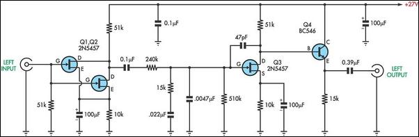
Powering the circuit with three 9V batteries in series provides a simple and effective solution for achieving the necessary voltage levels while keeping current consumption low at only 3 mA. This low power requirement makes the circuit suitable for portable applications or battery-operated devices, enhancing its versatility in various audio setups.There are two types of pre-amplifiers for magnetic phono cartridges. An example of the most common type is the one described in the March 2002 issue of SILICON CHIP. It has the RIAA equalisation network in the feedback loop. The second type was previously used in valve circuits which typically had no feedback loop and used passive RC networks to p rovide the phono equalization. This experimental preamp was put together using inexpensive FETs to compare the performance of these two types of preamp. The first stage, consisting of Q1 and Q2, is a simple FET audio amplifier, where the FETs are connected in parallel to reduce noise.
This is followed by a passive RIAA network consisting of 240kO and 15kO resistors and the associated 0. 1OF. 022OF and. 0047OF capacitors. Some of the gain loss in the passive network is then made up by FET Q3. It also has a 51kO drain resistor and is buffered by bipolar transistor Q4 which is connected as an emitter-follower stage.
All resistors are 1% tolerance metal film type while the capacitors for equalization are MKT polyester types. Ideally, the Idss of all FETs should be matched for both channels. Resistors R3 and R8 should be adjusted so that the drain voltage in each stage is between 13V and 14V, to give symmetrical signal clipping.
The power supply can be three 9V batteries connected in series. Current consumption is only 3mA for the stereo circuit. 🔗 External reference
Related Circuits
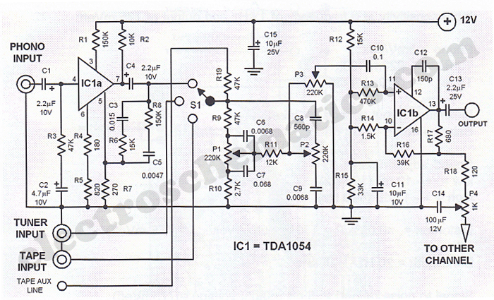
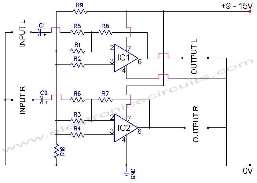
This Hi-Fi stereo preamplifier circuit is designed using the TDA1054 integrated circuit from SGS. The TDA1054 is a 16-pin DIL package that incorporates two separate preamplifier circuits. It is a low-noise preamplifier with minimal complications in the design process....
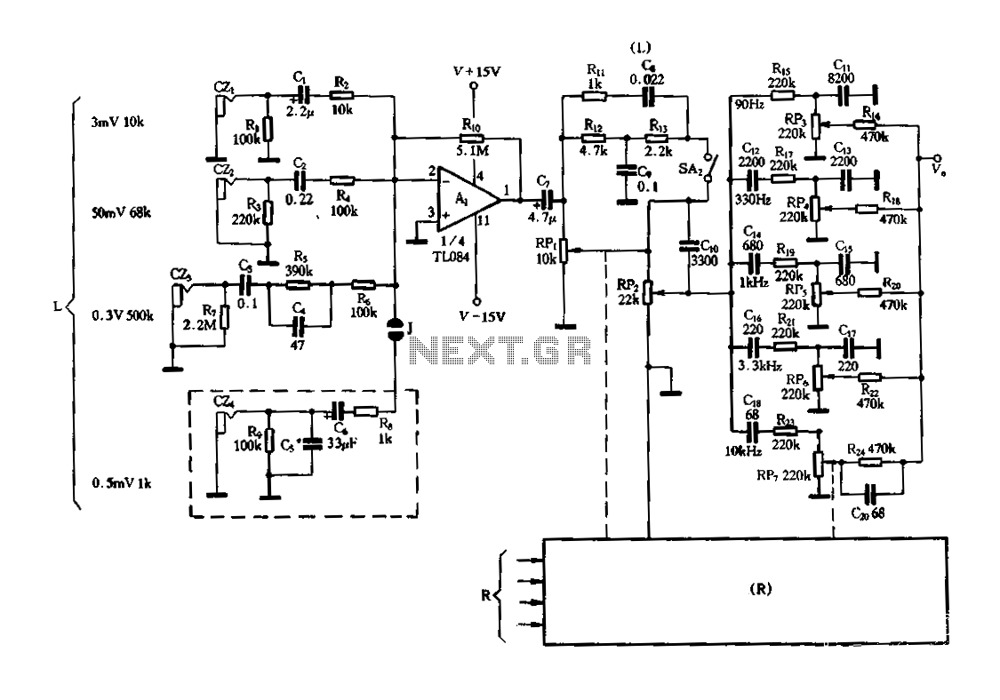
Figure 3-25 illustrates a hybrid circuit featuring four input preamplifiers. The components C1, C2, C3, and C4 can accept signals from a microphone, line, phono, and crystal head respectively. The configuration allows for the individual or simultaneous entry of...
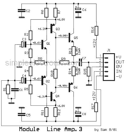
This is a simple low-impedance preamplifier circuit diagram used to amplify an audio signal. The circuit operates with a 12V DC power source and is straightforward due to its minimal component count. The low-impedance preamplifier circuit is designed to enhance...
741 Stereo PreAmplifier Circuit Diagram. This preamp circuit provides better than 20dB gain in each channel. PARTS LIST R1 -.. The 741 stereo preamplifier circuit is designed to amplify audio signals with a gain of over 20 dB in each...
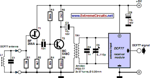
A popular project among microcontroller enthusiasts is to build a radio-controlled clock. Tiny receiver boards are available, equipped with a pre-adjusted ferrite antenna, which receive and demodulate the DCF77 time signal broadcast from Mainflingen in Germany. The DCF77 signal...
This is a simple microphone preamplifier circuit which you can use between your microphone and stereo amplifier. This circuit amplifier microphone suitable for use with normal home stereo amplifier line/CD/aux/tape inputs. This microphone preamplifier can take both dynamic and...