
DCF77 Preamplifier
The radio-controlled clock project utilizes a microcontroller to decode the DCF77 time signal, which is transmitted at a frequency of 77.5 kHz. The receiver module typically incorporates a ferrite antenna that captures the signal, but in areas where reception is weak, the design can be enhanced with a preamplifier. The preamplifier stage is critical for improving the signal quality before it reaches the microcontroller.
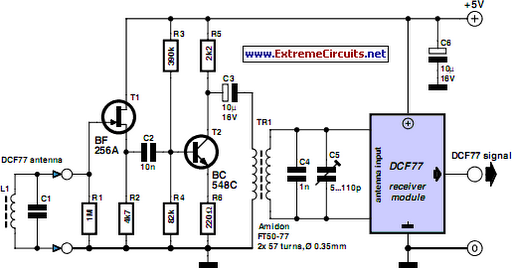
The preamplifier design includes a source follower transistor (T1) that ensures minimal loading on the antenna, preserving the quality of the received signal. Following this, a bipolar transistor (T2) is employed to amplify the signal by approximately 5 dB, which is essential for maintaining signal integrity when interfacing with the DCF77 module.
To couple the amplified signal to the DCF77 module, a transformer is used. The secondary side of this transformer, along with capacitors C4 and C5, creates a resonant circuit that must be accurately tuned to resonate at the DCF77 carrier frequency. Proper tuning is achieved using an oscilloscope to monitor the output signal amplitude while adjusting the trimmer capacitor (C5). The use of a signal generator to inject a known sine wave into the circuit allows for precise tuning, ensuring optimal performance of the receiver system.
The choice of transformer is significant; it must be designed to operate effectively at the resonant frequency of 77.5 kHz. The prototype's use of the FT50-77 core, with its specific winding configuration, illustrates a practical implementation. For further flexibility, transformers with adjustable cores can be utilized, allowing for fine-tuning of the resonant frequency without the need for additional trimmer capacitors. This detailed approach to designing the radio-controlled clock ensures that it can achieve reliable timekeeping even in less-than-ideal reception conditions.A popular project among microcontroller aficionados is to build a radio-controlled clock. Tiny receiver boards are available, with a pre-adjusted ferrite antenna, that receive and demodulate the DCF77 time signal broadcast from Mainf lingen in Germany. DCF77 has a range of about 1, 000 miles. All the microcontroller need do is decode the signal and output the results on a display. The reception quality achieved by these ready-made boards tends to be proportional to their price. In areas of marginal reception a higher quality receiver is needed, and a small selective preamplifier stage will usually improve the situation further. The original ferrite antenna is desoldered from the receiver module and connected to the input of the preamplifier.
This input consists of a source follower (T1) which has very little damping effect on the resonant circuit. A bipolar transistor (T2) provides a gain of around 5 dB. The output signal is coupled to the antenna input of the DCF77 module via a transformer. The secondary of the transformer, in conjunction with capacitors C4 and C5, forms a resonant circuit which must be adjusted so that it is centered on the carrier frequency.
An oscilloscope is needed for this adjustment, and a signal generator, set to generate a 77. 5 kHz sine wave, is also very useful. This signal is fed, at an amplitude of a few milli-volts, into the antenna input. With the oscilloscope connected across C4 and C5 to monitor the signal on the output resonant circuit, trimmer C5 is adjusted until maximum amplitude is observed. It is essential that the transformer used is suitable for constructing a resonant circuit at the carrier frequency.
Our proto-type used a FT50-77 core from Amidon on which we made two 57-turn windings. It is also possible to trim the resonant frequency of the circuit by using a transformer whose core can be adjusted in and out. In this case, of course, the trimmer capacitor can be dispensed with. 🔗 External reference
Related Circuits
This circuit is mainly intended to provide common home stereo amplifiers with a microphone input. The battery supply is a good compromise: in this manner the input circuit is free from mains low frequency hum pick-up and connection to...
This assembly is designed for amateurs who possess a collection of vinyl records and wish to convert them into a digital format on a personal computer. Alternatively, they may want to enjoy an old, cherished LP collection through their...
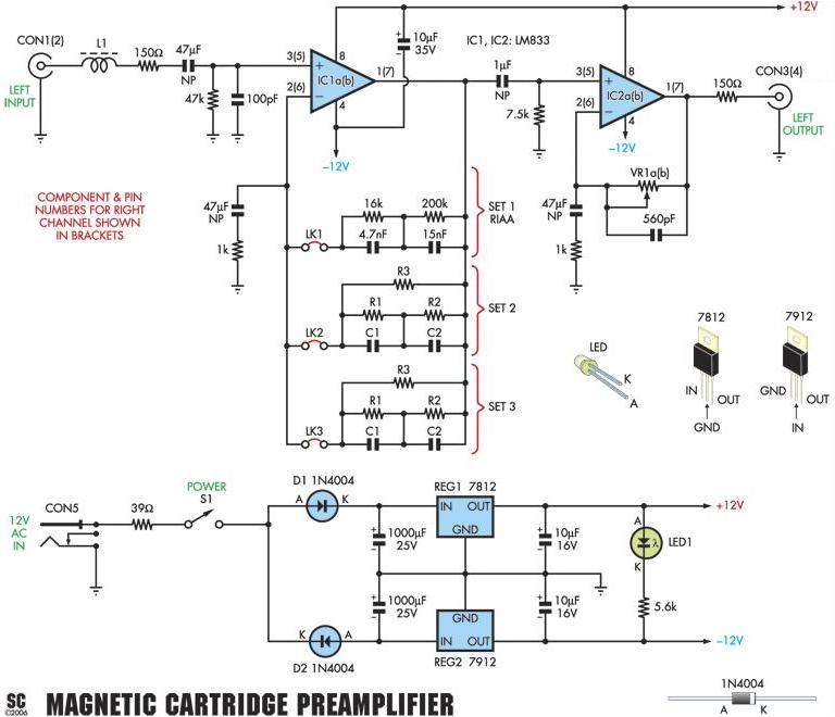
Mark builds and tests the DIY Moving Magnet (MM) Phono Preamplifier Kit that was featured in Silicon Chip Magazine, August 2006. The kit comes complete with everything you need except for an enclosure and a power supply (AC wall...
The circuit utilizes two 2N3819 FETs arranged in a cascode configuration. The lower FET functions in common source mode, while the upper FET operates in common gate mode, achieving full high-frequency gain. The lower FET is adjustable, enabling tuning...
Preamps may in some cases use a simple regulator, with the supplies taken from the main amp power supply. This can be a problem if the main amp is of very high power, as the supply voltage will be...
The preamplifier in question is engineered to interface with various audio devices such as CD players, tuners, and tape recorders. Its primary function is to provide an alternating current (AC) voltage gain of 4, an attribute that allows it to...