
Band 2 Preamplifier
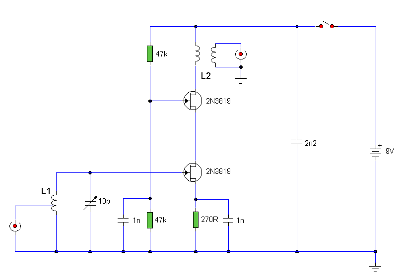
The described circuit employs a cascode configuration, which is beneficial for enhancing gain while maintaining stability and bandwidth. The lower 2N3819 FET, configured in common source mode, provides the initial amplification. This configuration is characterized by a high input impedance and a moderate output impedance, making it suitable for the amplification of weak signals.
The upper 2N3819 FET operates in common gate mode, which is advantageous for high-frequency applications. This configuration allows for a lower output capacitance, thereby improving the frequency response of the circuit. The common gate arrangement effectively isolates the lower stage from the load, reducing the Miller effect and enhancing overall gain performance.
Tuning capability is an essential feature of the circuit, facilitated by the adjustable lower FET. This tunability allows for the selection of a specific frequency, optimizing the circuit's performance for particular stations. The tuning mechanism can be implemented using a variable resistor or a similar component that alters the gate voltage of the lower FET, thus adjusting its operating point.
Coil details, which are crucial for determining the resonant frequency and impedance matching of the circuit, will further influence the overall performance. The choice of inductance and quality factor of the coils used in conjunction with the FETs will impact the efficiency and selectivity of the circuit. Proper attention to these components will ensure that the circuit achieves its intended high-frequency gain while maintaining stability and fidelity in signal processing.The circuit uses two 2N3819 FET`s in cascode configuration. The lower FET operates in common source mode, while the upper FET, operates in common gate, realising full high frequency gain. The bottom FET is tunable allowing a peak for a particular station. Coil details follow: 🔗 External reference
Related Circuits
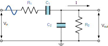
Electronics tutorial on the passive band pass filter circuit, which includes the passive RC band pass filter's first-order frequency response and Bode plot. The passive band pass filter circuit is a fundamental electronic component that allows signals within a specific...

This circuit exhibits an exceptionally fast high-frequency response, as demonstrated by applying a 100 kHz square wave to the input. All graphs were produced using Tina Pro. The circuit's design is optimized for high-frequency applications, showcasing rapid response times that...
This preamplifier is designed to interface with CD players, tuners, tape recorders, and similar devices, providing an AC voltage gain of 4 to drive less sensitive power amplifiers. Given that modern Hi-Fi home equipment often comes with small loudspeaker...
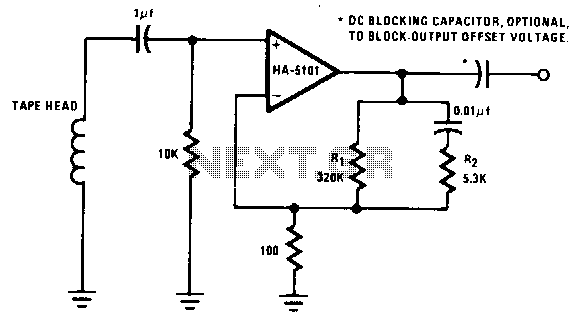
The preamplifier is designed to offer a low-frequency boost at 50 Hz, maintain a flat response up to 3 kHz, and attenuate high frequencies above 3 kHz. Compensation for variations in tape and tape head performance can be accomplished...
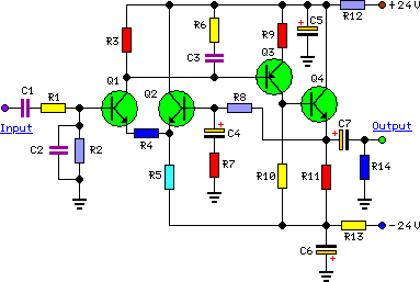
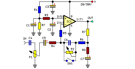
To complement the 60 Watt MOSFET Audio Amplifier, a high-quality preamplifier design was necessary. A discrete component topology, utilizing ±24V supply rails, was chosen, maintaining a minimal transistor count while still achieving low noise, very low distortion, and a...
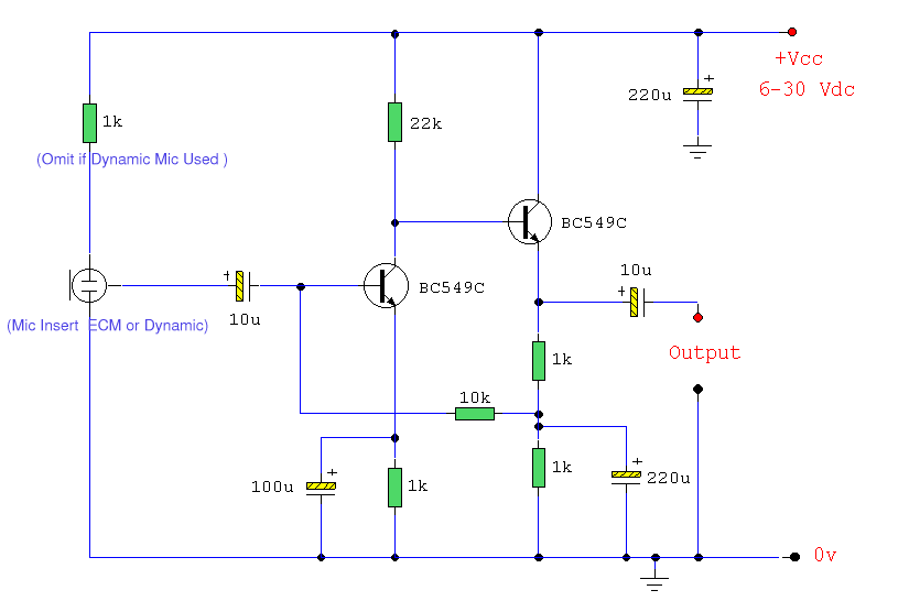
Both transistors should be low noise types. In the original circuit, BC650C was used, which is an ultra-low noise device. These transistors are now hard to find, but BC549C or BC109C are good replacements. The circuit is self-biasing and...