
Stereo Preamplifier with Bass-boost

A common issue with contemporary Hi-Fi home equipment is the tendency to feature smaller loudspeaker cabinets. While this design choice may offer certain advantages, it often results in the bass frequency range being compromised. To address this issue, the described preamplifier circuit incorporates a bass-boost feature. This additional feature is designed to compensate for the reduced bass frequency range, thereby ensuring a more balanced and fuller audio output.
The bass-boost feature in this circuit is adjustable, providing users with the flexibility to set the bass-boost level according to their preference. This is achieved through the use of a variable resistor, which can adjust the bass-boost from 0 to a maximum of +16dB at 30Hz. This range of adjustment allows for a significant enhancement of the bass output, particularly beneficial for audio content that is rich in low-frequency sounds.
However, if a fixed, maximum boost value is desired, the variable resistor can be bypassed. Instead, a switch can be used to maintain a constant bass-boost level. This option could be particularly useful in situations where a consistent, high-level bass output is required, such as during playback of certain genres of music or during specific audio experiences. This flexibility in controlling the bass-boost level makes the preamplifier versatile and adaptable to a variety of audio setups and user preferences.This preamplifier was designed to cope with CD players, tuners, tape recorders etc., providing an ac voltage gain of 4, in order to drive less sensitive power amplifiers. As modern Hi-Fi home equipment is frequently fitted with small loudspeaker cabinets, the bass frequency range is rather sacrificed.
This circuit features also a bass-boost, in order to overcome this problem. You can use a variable resistor to set the bass-boost from 0 to a maximum of +16dB @ 30Hz. If a fixed, maximum boost value is needed, the variable resistor can be omitted and substituted by a switch. 🔗 External reference
Related Circuits
In addition to its primary function as a headphone amplifier, the circuit is suitable for various applications requiring a wide bandwidth low power amplifier. It is constructed using an operational amplifier (op-amp), with its output current enhanced by a...
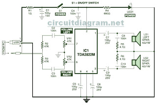
This is the circuit diagram of a USB-powered computer speaker, commonly referred to as multimedia speakers for PCs. The circuit features a single-chip design, operates on a low-voltage electrical power supply, is compatible with USB power from computers, and...
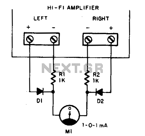
Play any stereo disc or tape and then set the amplifier to mono. Adjust the left and right channel balance until meter Ml indicates zero; then the left and right output levels are identical. To implement a system that allows...
A microphone amplifier designed for use with either Electret Condenser Microphone (ECM) inserts or dynamic inserts, constructed with discrete components. The preamplifier circuit is self-stabilizing and sets its quiescent point at approximately half the supply voltage at the emitter...
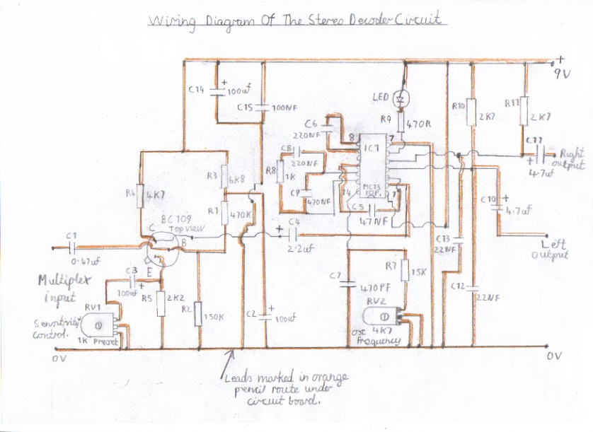
This section of the site presents a stereo decoder circuit suitable for both pulse counting FM receivers and various types of FM tuners, including older valve types that utilize a Foster Seeley or Ratio Detector. The MC1310P stereo decoder...
A block diagram of the stereo TV decoder is presented. It illustrates the overall relationships between the separate sections of the circuit. The decoder section revolves around IC1, a standard 4.5-MHz audio demodulator. The output of IC1 is routed...