
Definition of a Hartley oscillator

The Hartley oscillator is a widely used electronic oscillator that is particularly valued for its simplicity and effectiveness in generating sine wave signals. The design is characterized by its use of two inductors, which can either be separate components or a single inductor with a center tap. This configuration allows for flexibility in tuning the oscillator's frequency by varying the inductance or capacitance in the tank circuit.
The tank circuit, consisting of the inductors and a capacitor, is responsible for determining the oscillation frequency. The feedback mechanism is crucial for sustaining oscillations; the feedback signal is derived from the voltage across one of the inductors or the tap point, which is then fed back to the input of the amplifier. This feedback loop is essential for maintaining the oscillation, as it reinforces the input signal.
Transistor configurations in Hartley oscillators can vary, with the most common being the Common Base, Common Emitter, and Common Collector arrangements. Each configuration affects the gain, input, and output impedance of the oscillator, allowing for optimization based on the specific application. The choice of NPN or PNP transistors will depend on the required circuit design and the polarity of the power supply.
The method of connection between the tank circuit and the amplifier circuit plays a significant role in the oscillator's performance. In a series-fed configuration, the tank circuit is directly in line with the power supply, which can influence the overall efficiency and output amplitude. In contrast, the shut-fed configuration allows for greater flexibility in how the amplifier interacts with the tank circuit, potentially improving stability and performance.
To calculate the frequency of oscillation accurately, it is essential to consider both the inductance values and the mutual inductance between the coils. The formula provided allows for precise determination of the frequency based on the selected components, facilitating the design of oscillators tailored for specific frequency requirements.
Overall, the Hartley oscillator remains a fundamental building block in various electronic applications, including RF transmission, signal generation, and waveform synthesis, due to its straightforward design and reliable performance characteristics.A Hartley Oscillator is a style of oscillator that uses two series connected inductors or an inductor with a center tapped coil, along with a capacitor. The tank circuit is formed by the inductor and the parallel capacitor. An oscillator circuit requires an amplifier which has a feedback path between the output and input. The feedback point for th e Hartley oscillator is between the two inductors, or the tap on the inductor, as shown in the diagram. The amplifier used in each of these circuit examples is a transistor; although any amplifier could be used.
Because the definition of a Hartley oscillator only defines the method of the feedback tap any transistor configuration may be use. The graphic below shows three different Hartley oscillators, each using a different transistor configuration: Common Base [CB], Common Emitter [CE], and Common Collector [CC].
The tuned circuit, or tank circuit is identical in each different layout. Either type of transistor may be used; note that the configuration graphic uses PNP transistors as examples, but the circuits use NPN transistors. The tuned circuit of an oscillator may be connected to the amplifier circuit in one of two ways. A series-fed oscillator uses a tank circuit which is in series with the same supply voltage used to drive the amplifier.
A shut-fed oscillator will have the tuned circuit in parallel with the amplifiers supply voltage. So that the amplifier draws its current directly from the supply, although there might be a bias component between the two. The frequency of oscillation is determined by the inductor(s) and capacitor values used in the tank circuit.
The basic equation for the Frequency of Oscillation, which includes the total inductance of both inductors [Lt] is used: Fo = 1 / [2 x 3. 1415 x (Lt x C)1/2]. The total inductance is calculated by the individual values of the inductors and their mutual inductance; so; Lt = L1 + L2 + M (the coupling factor).
Another example of a Hartley oscillator is shown below. The circuit uses a transistor again, but that could easily be replaced by a FET. A PNP transistor could also be used if the polarity of the supply voltage was changed. The coupling capacitors are labeled in the circuit, but have nothing to do with the tuned circuit. The variable capacitor in the LC circuit is the one that forms part of the tuned circuit. 🔗 External reference
Related Circuits
The Colpitts oscillator circuit schematic is closely related to the shunt-fed Hartley oscillator, with the primary distinction being in the tank circuit design. In the Colpitts oscillator, two capacitors are utilized in place of divided coils. The basic feedback...
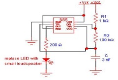
This article offers valuable information for creating a specific oscillator or pulse generator using integrated circuits (ICs), resistors, and capacitors, regardless of the version of the 555 IC utilized. The 555 timer IC is a versatile component widely used in...
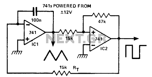
This circuit generates a triangle waveform and a square waveform simultaneously. It is self-starting and does not have latch-up issues. IC1 functions as an integrator with a slew rate determined by the capacitor (CT) and resistor (RT). IC2 acts...
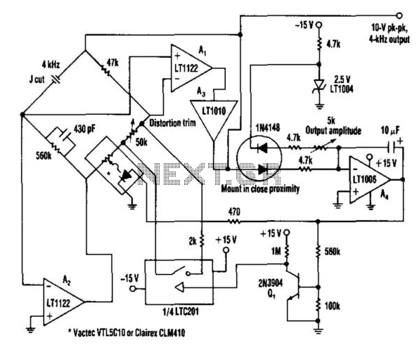
This oscillator utilizes a bridge circuit with an optoisolator functioning as a gain-control device. The resultant distortion can be maintained at 9 ppm (0.0009%) with appropriate adjustments. The oscillator circuit described operates using a bridge configuration, which is a common...
Signals with a known frequency but an unknown phase can be detected using an in-phase signal and a signal that is shifted by 90 degrees, a method commonly utilized in lock-in amplifiers, synchronous detectors, and frequency-response analyzers. The signal...
Rf = 100 k preset. The slider is positioned approximately a quarter of the way around. This component is utilized to control the gain, which should be minimized while ensuring the oscillator starts reliably. Zener diodes limit the oscillator...