
Very Low Distortion Oscillator

The oscillator circuit described operates using a bridge configuration, which is a common approach in precision applications. The bridge circuit typically consists of four resistive components arranged in a diamond shape, allowing for the measurement of voltage differences that can be used to control the output signal. In this specific design, an optoisolator is integrated into the bridge, serving as a gain-control device.
Optoisolators, also known as optocouplers, are crucial in providing electrical isolation between different parts of a circuit while allowing signal transfer. This isolation is particularly beneficial in preventing ground loops and protecting sensitive components from voltage spikes or noise from other parts of the system.
The gain-control feature is essential for maintaining low distortion levels in the oscillator's output. Distortion, measured in parts per million (ppm), indicates the degree to which the output deviates from a pure sine wave. In this case, the design achieves an impressive distortion level of 9 ppm (0.0009%) through careful calibration and adjustment of the circuit parameters.
To achieve such low distortion, it is vital to select high-precision components and implement a robust feedback mechanism within the oscillator. The feedback loop can help stabilize the gain and ensure consistent performance over varying operating conditions. Additionally, the adjustment process may involve tuning the resistive elements in the bridge or modifying the characteristics of the optoisolator to optimize the gain and minimize any potential distortion.
Overall, this oscillator design exemplifies the integration of advanced components and techniques to achieve high performance in electronic signal generation, making it suitable for applications requiring precise frequency stability and low distortion. This oscillator uses a bridge circuit with an optoisolator as a gain-control device. The resultant distortio n can be held to 9 ppm (.000 9%) with proper adjustment.
Related Circuits
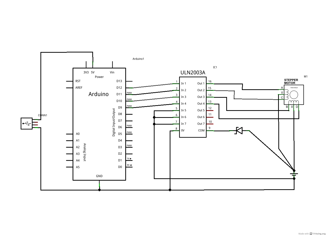
The ULN2003A and Zener diode are components from the driver board within the same device. The motor in question has five wires, while the schematic depicts a six-wire motor. It is assumed that the difference lies in the fact...
A high voltage power supply is a valuable source that can be effectively used in various applications, such as biasing gas-discharge tubes and radiation detectors. This type of power supply can also serve as a protective measure, such as...
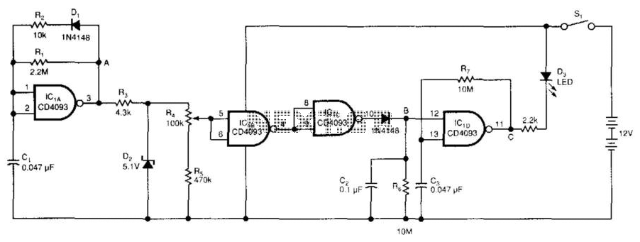
The low-voltage battery detector employs a CD4093 Schmitt trigger alongside a capacitor functioning as a 1-bit dynamic RAM. The circuit is designed to conserve power through a periodic testing method. Components IC1A, CI, R1, R2, and D1 produce a...
A pH meter is a precise voltmeter that measures the generated voltage of pH electrodes. The demand for such a meter is significant. A pH meter operates by utilizing a combination of a glass electrode and a reference electrode. The...
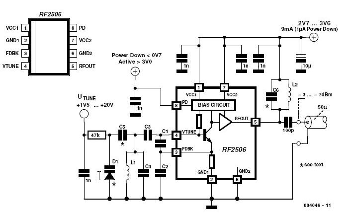
Nowadays, it is no longer necessary to use discrete components to build oscillators. Instead, many manufacturers provide ready-made voltage-controlled oscillators. In contemporary electronic design, the reliance on discrete components for oscillator construction has diminished significantly. The availability of integrated voltage-controlled...
This is a subwoofer low-pass filter circuit, which is another variant based on the discharge from ST Microelectronics' TL062. The TL062 is a dual high-input impedance J-FET operational amplifier characterized by low power consumption and a high slew rate....