
SINE WAVE OSCILLATOR

The described circuit employs a dual op-amp configuration to achieve a sine wave output through a systematic approach of generating a square wave and subsequently filtering it. The astable oscillator configuration of A1 utilizes resistors R1 and capacitors C1 to determine the desired frequency of oscillation, establishing a square wave output. The output of A1 is then processed through the Sallen-Key low-pass filter, which is configured to allow the fundamental frequency of the square wave to pass while attenuating higher harmonics, resulting in a cleaner sine wave output.
The feedback mechanisms in the circuit are crucial for maintaining the desired oscillation characteristics. The gain control via the Rf preset ensures that the system operates at the edge of stability, allowing the oscillator to start reliably without excessive distortion. The use of Zener diodes introduces a level of output limitation that is beneficial in preventing saturation, although at the cost of some waveform fidelity. The substitution of normal diodes for Zener diodes can be employed to tailor the output voltage levels for specific applications, such as interfacing with headphones.
Component selection is based on established formulas that relate frequency, resistance, and capacitance, ensuring that the circuit can be fine-tuned to meet specific performance criteria. The matching of resistor values is also important for maintaining frequency accuracy, as discrepancies can lead to unintended variations in output frequency.
Overall, this sine wave generator circuit is versatile and can be adapted for various applications, including audio signal generation and testing. The straightforward assembly process and reliance on common components make it accessible for rapid prototyping and experimentation in electronic design.Rf = 100 k preset - The slider is set about a quarter of the way round. This is used to control the gain. The gain should be as small as possible consistent with the oscillator starting up reliably. The zener diodes limit the oscillator output by decreasing the amplifier gain if the output rises above their breakdown voltage. They also decrease th e accuracy of the sine wave shape. However if the diodes are not there, the amplifier limits and the distortion is much worse. For a much smaller audio output, replace the Zener diodes in series with normal diodes in parallel. The output will now be about +/- 0. 7 volts, suitable for headphones or the input of an audio amplifier. This circuit is designed to have a gain of exactly 1. If the gain were less, the oscillations would die away. If the gain were more, the pure sine wave would get bigger until the op amp limited and the wave would become clipped. If the output is too small, the diodes don`t conduct. This makes the gain higher. If the output is too large, the diodes to conduct and this negative feedback decreases the gain. When the output is just right, the gain is one. The resistors and capacitors (R and C) provide positive feedback. At the frequency of oscillation, the positive feedback is in phase and this reinforces the oscillations.
At other frequencies, this is not the case so the oscillator frequency is controlled. Rf provides negative feedback. With too much negative feedback, the oscillator would fail to start. With too little feedback, the output would increase until the oscillator limited. The following article will show you how to use two op amps to make a simple sine wave generator. DO NOT USE A HIGH SPEED OP AMP - USE A CHEAP SLOW ONE, TRANSISTOR NOT CMOS. A high speed one would just give you oscillation problems. Any old TTL one you got in the drawer will work just fine. Finally, the output voltage is not critical; we can adjust for that later. Use your 12 volt supply and get a sine that doesn`t clip. If it ends up at P-P 10 v or 9 v or even 8 v it doesn`t matter. In various design and test situations, a sine wave signal with an arbitrary frequency may be needed. The following design, and accompanying Excel spreadsheet implement a sine wave generator that can be quickly assembled with a dual op amp and small number of resistors and capacitors. Figure 1 shows the schematic for the quick sine wave generator: This circuit generates a sine wave by first generating a square wave, at the required frequency, with amplifier A1 that is configured as an astable oscillator with the frequency determined by R1 and C1.
The two-pole low pass filter, using A2, filters the square wave output from A1. The filter is a unity gain Sallen-Keys filter with its cut off frequency equal to the square wave frequency from A1. The square wave is made up of the fundamental frequency and the odd harmonics of the fundamental frequency.
The filter removes most of the harmonic frequencies and the fundamental frequency remains at the output of A2. The fundamental frequency component of a square wave is about 1. 27 times the peak amplitude of the square wave and the amplitude of the sine wave output will be approximately 87 percent of the peak of the square wave.
The peak of the square wave will depend on the amplifier`s supply voltage and the output swing specification of the amplifier. Additionally, the peak of the square and the sine wave will track changes in the amplifier`s supply voltage.
In this design, the frequency is specified along with the value of C1 and based on these values, the values of R1, C2, C3, R4, and R5 are calculated. The values of R2, R3 and R4 are 1K Ohms and should be matched in value to help minimize errors in the actual frequency of operation compared to the calculated frequency of operation.
The equations for the component selection follow. The frequency, F, is the required sine wave frequency. The value f 🔗 External reference
Related Circuits
A 2N366 is configured as an audio feedback oscillator using an audio transformer. Adjust R1 for proper operation and the desired audio note. The circuit utilizes a 2N366 transistor, which is a general-purpose NPN transistor, serving as the primary active...
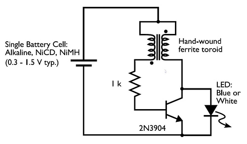
A transformer with two input leads and three output leads was used. An LED was connected to two of the output leads, and when a dead AA battery was connected to the input leads, the LED blinked for a...
In the image above, Oscium's iMSO-104 oscilloscope is measuring the output waveform of an infrared receiver (IR Rx). The iPad and iMSO serve as the oscilloscope to measure the receiver's output signal as the alignment between the transmitter and...

The term VCXO refers to a Voltage Controlled Crystal Oscillator. The frequency of this oscillator can be fine-tuned by varying the control voltage. VCXO clock generators are utilized in a range of applications, including digital telecommunications. VCXO circuits are essential...
This is a simple scheme for a bridge oscillator. It provides a nice sinusoidal signal. This type of oscillator uses an op-amp. The weakening of the oscillating member (R1, R2, C1, C2) is 3x. To compensate, the attenuated signal...
This circuit uses the versatile MAX038 function generator. Although in this circuit some of the advanced characteristics of this IC are disabled, you can generate Sine, Triangle, Square waves (adjusting A0 and A1 pins see datasheet on www.maxim-ic.com if...