
Design and realizing of the electric transmission line monitoring system
The design's architecture is built to enhance the monitoring and analysis of electric transmission lines effectively. The MSP430F135 microcontroller serves as the central processing unit, leveraging its low power characteristics to ensure long-term operation without frequent battery replacements. The integration of various sensors and measurement circuits allows for real-time data acquisition and processing, essential for maintaining optimal performance in electric transmission systems.
The DSP chip's capabilities to perform complex calculations such as active and reactive power, as well as harmonic analysis, provide valuable insights into the electrical system's behavior. This functionality is crucial for utilities to manage loads efficiently and ensure reliability in power delivery. The system's ability to communicate with external devices via SPI and serial communication enhances its flexibility, allowing for integration with existing infrastructure.
In terms of user interaction, the human-machine interface, featuring an LCD display and a keyboard module, enables operators to easily access and interpret data. The acousto-optic alarm circuit serves as an effective alert mechanism, notifying users of any anomalies in the transmission line parameters. Overall, this design represents a comprehensive solution for monitoring electric transmission lines, combining advanced measurement techniques with user-friendly interfaces to facilitate effective management and control.Difficult to observe in order to solve the leaning phase in adjusting the electric transmission line manually, record and difficult and normalizing three major difficult problems this difficultly. This design passes the design of the software and hardware, have realized it for longer time, do not have it to the electric current in the electric tra
nsmission line disconnectedly, voltage, zero sequence current, power factor, active power, reactive power, apparent power, group involve the monitoring, record of the harmonic electric energy and store. This design adopts MSP430F135 one-chip computer in order to control the core, combine voltage, current transformer, DSP electric energy chip, human-machine interface, acoustooptic alarm circuit and signal processing circuit, etc.
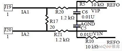
and realize the supervision on electric transmission line parameter, system this can data that gather for a long time carry on curve analyze in upper computer in the plate with leave U in, offer science, reliable basis for adjusting circuit load in the utility. This design chooses DSP electric energy chip, chip this have seven No. second order 16 sigma-delta ADC, basic reference voltage output, the voltage, electric current are sampled, fundamental wave, harmonic wave and metric signal processing circuit of energy frequency, have SPI communication interface at the same time, and support gain to noise temperature ratio of the whole digital domain, phase correction.
Can automatic computation active power, reactive power, look at year power and power factor. Inside has voltage that monitors the circuit, work and go on normally when can guarantee power up and power down. This design can carry on high-accuracy measuring, input the dynamic operating range 1000: 1, Guarantee the non-linear error in emasurement is in 0.
1% at the same time. Support gain to noise temperature ratio and phase compensation, the non-linear compensation of the trickle. The voltage, precision of mean value of electric current are superior to 0. 5%. MSP430 one-chip computer is 16 one-chip computers of low power consumption, has typical SOC characteristics, integrates a large amount of peripheral hardware.
Especially its internal Integrated baud rate trimmer, can make MCU it lower than arbitrary Jingzhen of 32 768 Hzs to be but unable to exceed MCU to upgrade that Jingzhen require Leave, work, choose communication have the intersection of baud rate and factor decimal to restrain from at the baud rate, namely: Can use the Jingzhen of the arbitrary frequency within the range of permission of baud rate. In addition, because the integrated temperature sensor within MSP430 MCU, can be in order to realize conveniently that pays compensating in examining the temperature of used pressure capsule of liquid level.
And the MSP430 series one-chip computer is made up of all kinds of module to different application, because of the characteristic of low power consumption of the used microcontroller, can use the normal operation of ordinary battery, realize and has not used disconnectedly normally for a long time. As shown in Fig. 1 the overall system is mainly by the host computer circuit of the one-chip computer, controlling circuit, signal measurement, acoustooptic alarm circuit, key set circuit, LCD Chinese character display circuit, power supply circuit and communication channel, etc.
make up. P1 mouth, as data link of system, DSP the intersection of electric energy and chip adopt the intersection of P3. 0 P3. 1 P3. 2 and mouth, insert MCU, used for, offer data that input to system, job signal passing P2. 5 one of the module of sound and light alarm exports and produces the warning sound. Keyboard module, through P2. 0, P2. 1 and the intersection of P2. 2 and mouth insert MCU, use 6 key set of control system for. The system controls LCD display unit through P1 mouth and P5. 0, P5. 1, serial communication is read and written through circuit c 🔗 External reference
Related Circuits

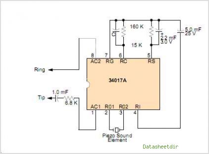
This circuit is designed for interfacing phone projects with the telephone line. It includes a ringer, has the capability to interrupt the wiring, and provides isolation for the project from the phone line. The circuit operates by integrating a ringer...
A Subaru Brumby has been in possession for an extended period. The mechanic has indicated that the engine is... The Subaru Brumby, a compact utility vehicle, features a robust engine that is essential for its performance and reliability. The engine...
It is widely recognized that power-saving regulations necessitate very low power consumption during standby conditions for all equipment continuously connected to mains power. In the standard version of the power supply, standby power consumption is approximately 9.0 W for...
The more one understands about any subject, the more interesting it becomes. As this article is read, it will be found that the subject of... A comprehensive electronic schematic typically involves various components, each serving a specific function in the...
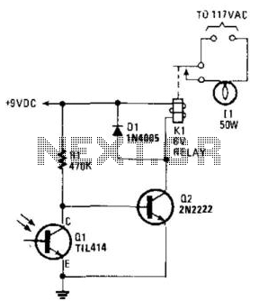
A phototransistor detects daylight. At dusk, it stops conducting, and Rl biases Q2, activating Kl, which turns on the light. At dawn, Ql begins to conduct, cutting off Q2. Kl deactivates, and the light turns off. The circuit utilizes a...

This circuit offers a distinctive solution to a prevalent power distribution issue at the system level. When the supply voltage to a remote board must travel through a lengthy cable, the voltage at the termination point may decrease to...
Warning: include(partials/cookie-banner.php): Failed to open stream: Permission denied in /var/www/html/nextgr/view-circuit.php on line 713
Warning: include(): Failed opening 'partials/cookie-banner.php' for inclusion (include_path='.:/usr/share/php') in /var/www/html/nextgr/view-circuit.php on line 713