
Simple Photoelectric Light Controller
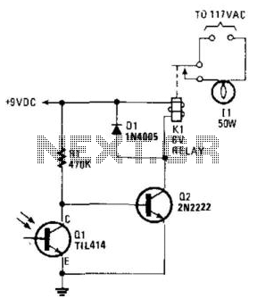
The circuit utilizes a phototransistor to monitor ambient light levels. During daylight, the phototransistor remains in a conductive state, allowing current to flow through it. As the sun sets and the light diminishes, the phototransistor transitions to a non-conductive state. This change in state is critical as it allows resistor Rl to provide biasing to transistor Q2. When Q2 is activated, it triggers relay Kl, which in turn powers the connected light source, illuminating the area.
As dawn approaches and light levels increase, phototransistor Ql begins to conduct again. This conduction effectively cuts off the biasing current to Q2, leading to its deactivation. Consequently, relay Kl is also deactivated, which turns off the light. The interplay between the phototransistor and the transistors provides an automatic lighting solution that responds to environmental changes, ensuring that lights are only on when needed.
In summary, this circuit design exemplifies efficient light control through the use of a phototransistor and associated components, creating an automated system that enhances convenience and energy efficiency. A phototransistor senses daylight. At dusk, it ceases to conduct and Rl biases Q2, activates Kl, and switches on the light. At dawn, Ql starts to conduct, and Q2 is cut off. Kl drops out and the light goes out. 🔗 External reference
Related Circuits
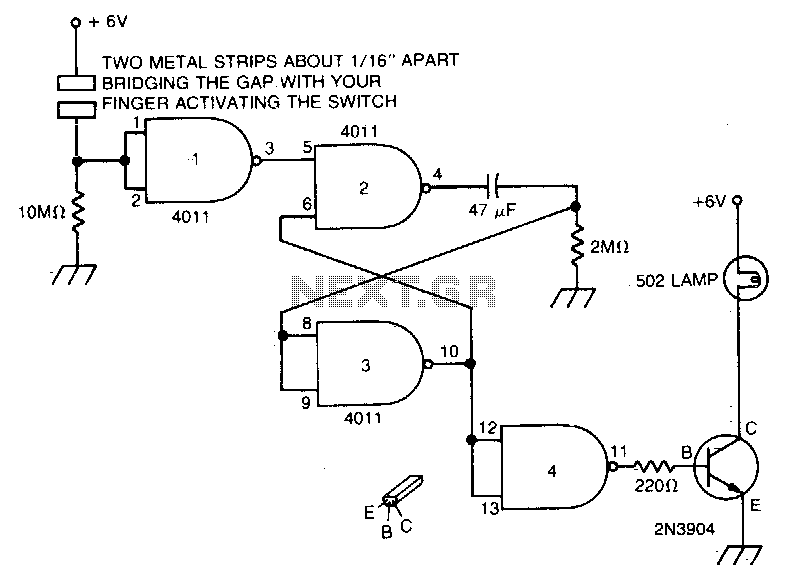
Touch the plate, and the light will turn on and remain on due to the 47 µF capacitor and the 2MΩ resistor for a duration determined by the timing resistor. The circuit described involves a touch-sensitive plate that activates a...
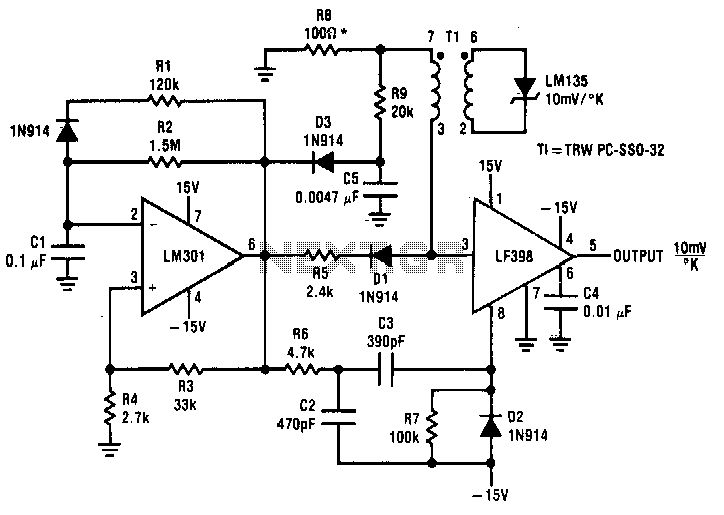
Both converters utilize CMOS inverters. Figure 105-1A illustrates a free-running circuit where both pulse duration and pulse pause are influenced by the temperature of diode D8. This configuration is suitable for applications where synchronization between the converter and other...
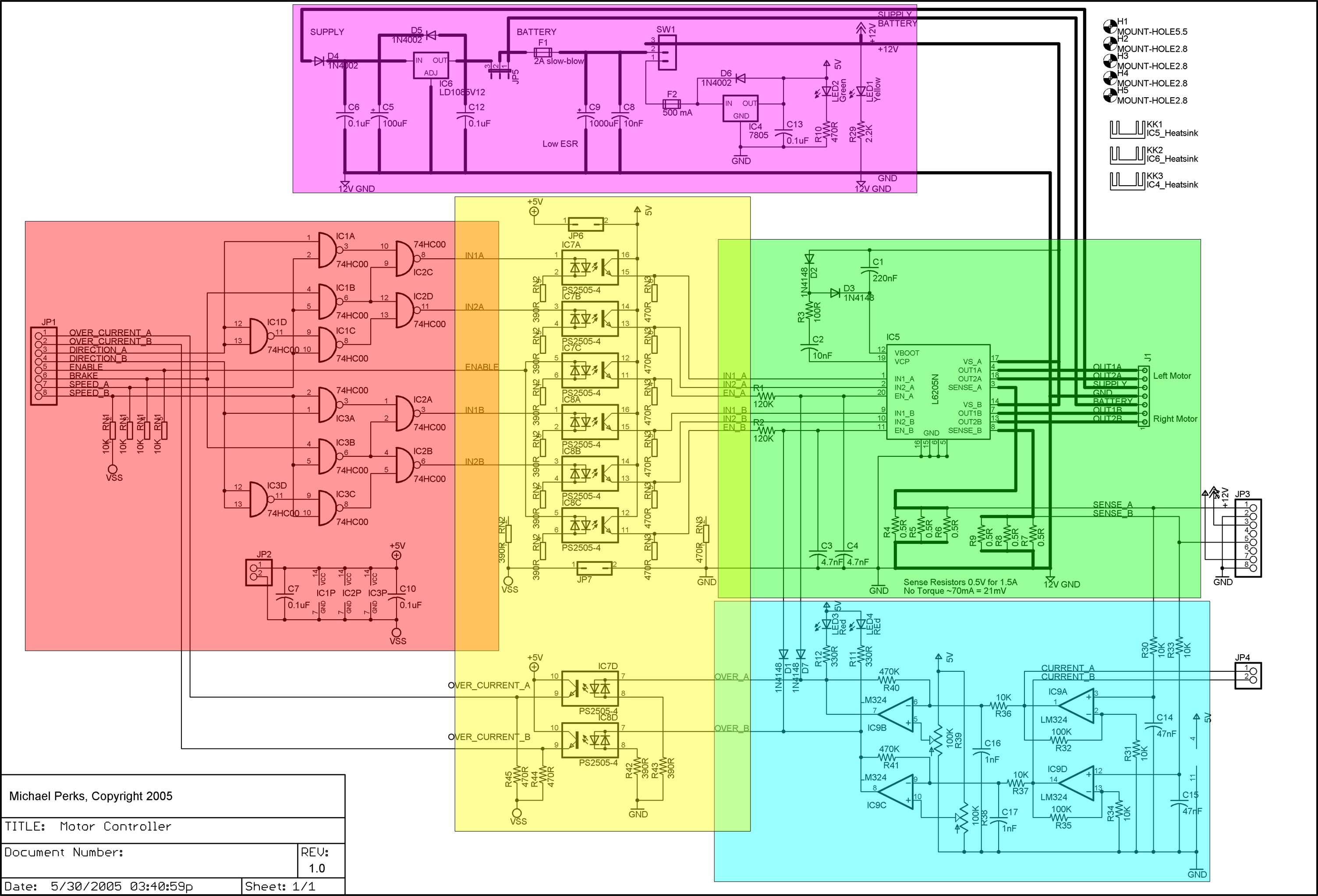
A dual DC motor controller employs an H-bridge controller chip. In addition to the standard features of the H-bridge driver chip, such as thermal and over-current protection, the circuit supports dual 12V/5V regulated power supplies, sign/magnitude and brake driver...
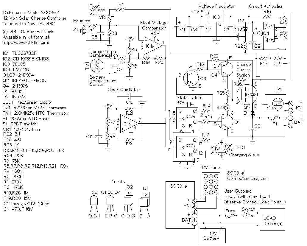
The SCC3 is a solar charge controller. Its function is to regulate the power flowing from a photovoltaic panel into a rechargeable battery. It features easy setup with one potentiometer for the float voltage adjustment, an equalize function for...
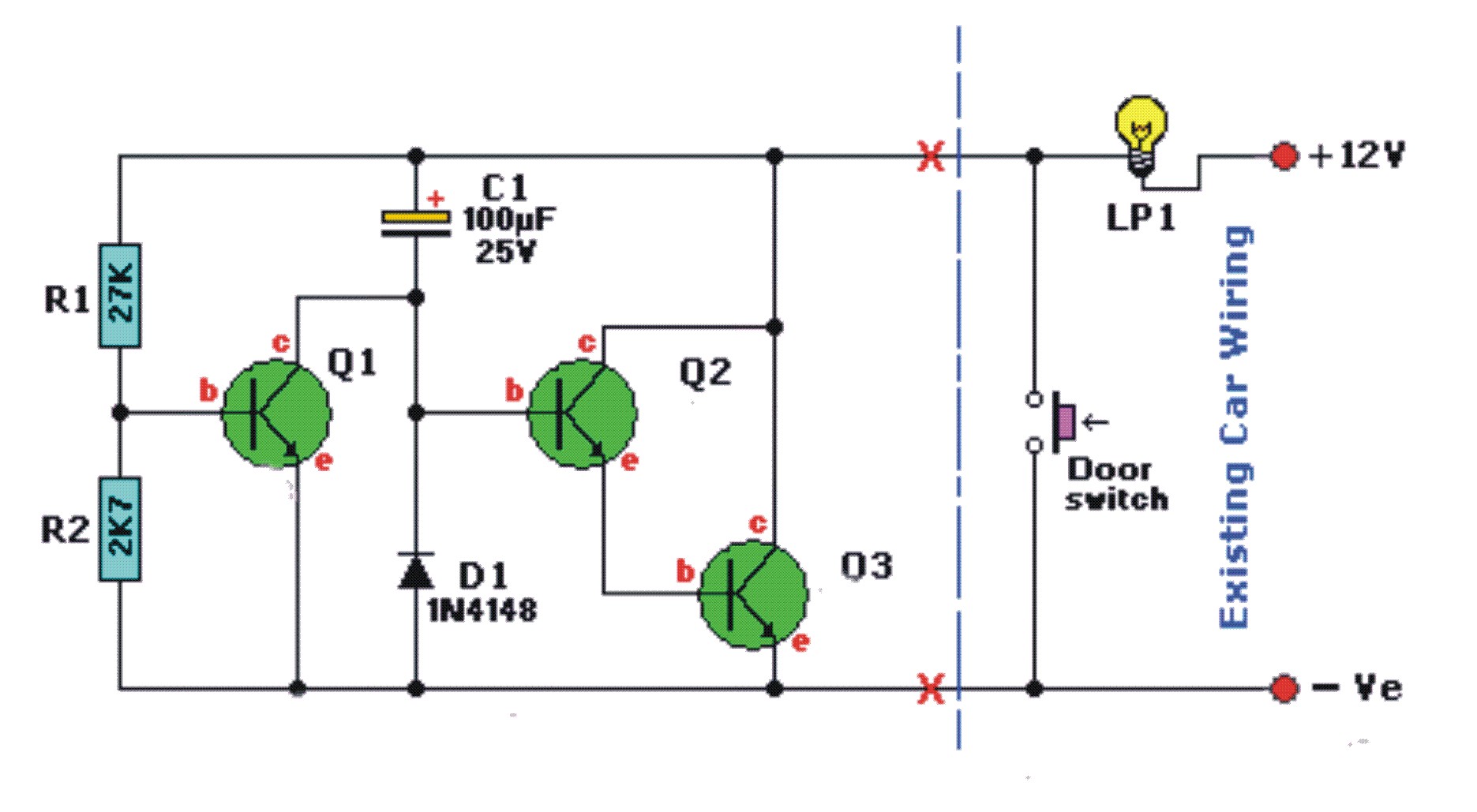
Any idea where I can obtain the schematics for a dome light dimmer to be used in a car? This device should illuminate the light when the door is opened and gradually dim and turn off when the door...
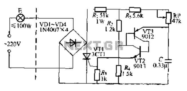
The circuit is a one-way ordinary transistor-triggered dimmer light circuit. It uses a complementary amplifier configuration with transistors VT2 and VT3 to form the thyristor trigger circuit for VT1. The circuit operates with a 220V alternating current through the...