
power supply design

A comprehensive electronic schematic typically involves various components, each serving a specific function in the overall circuit design. In a basic schematic, elements such as resistors, capacitors, inductors, diodes, and transistors are represented by standardized symbols. Each component is connected by lines, which represent the electrical connections between them.
Resistors are used to limit current flow and divide voltages, while capacitors store and release electrical energy, often used for filtering applications. Inductors, on the other hand, store energy in a magnetic field when electrical current passes through them. Diodes allow current to flow in one direction only, providing rectification in power supply circuits. Transistors function as switches or amplifiers, controlling the flow of current in a circuit.
Power sources, such as batteries or power supplies, are typically indicated in a schematic, providing the necessary voltage and current for the circuit to operate. Ground connections are also crucial, serving as a reference point for voltage levels in the circuit.
In addition to these components, a well-designed schematic may include labels for each part, values for components (like resistance in ohms or capacitance in farads), and notes on the operation of the circuit. This information aids in understanding the functionality and interconnections of the circuit, facilitating troubleshooting, and further development.
Overall, a detailed electronic schematic serves as a vital tool for engineers, allowing for the effective design, analysis, and implementation of electronic systems.Hello world!, The more you understand about any subject, the more interesting it becomes. As you read this article you`ll find that the subject of.. 🔗 External reference
Related Circuits
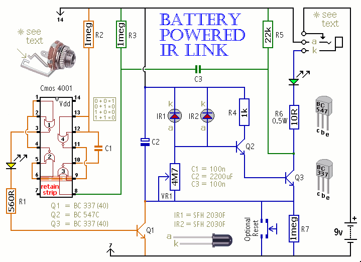
This is a battery-powered infrared (IR) link that can be utilized in multiple rooms. The standby current is exceptionally low, resulting in excellent battery life. The circuit is designed to shut down when faced with extraneous IR radiation, effectively...
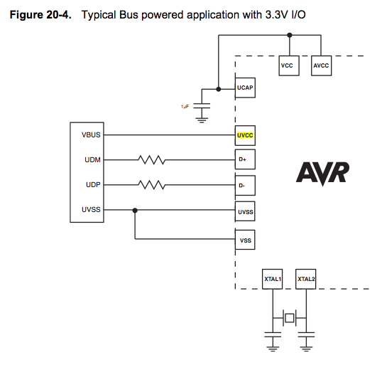
Since the microcontroller unit (MCU) is powered through USB, the common zero voltage should align with the supply voltage and thus be connected to the 0V (UVSS) line. In electronic circuit design, it is essential to ensure that the ground...
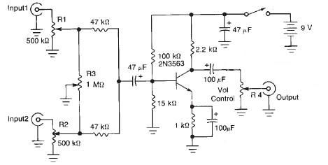
This audio mixer circuit diagram electronic project is designed using a few common electronic components. The audio mixer circuit project has two input channels. The input signal can be independently controlled using the R1 and R2 variable resistors. The...
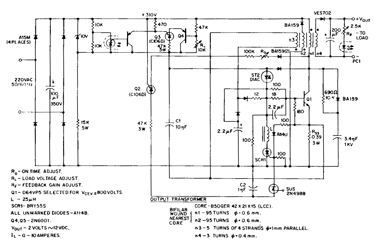
This low-voltage, high-current output switching power supply operates from a 220 VAC input. In this circuit, an ST2 diac relaxation oscillator, along with Q3, C1, and the diac, initiates the conduction of the output switching transistor Q1. The on-time...
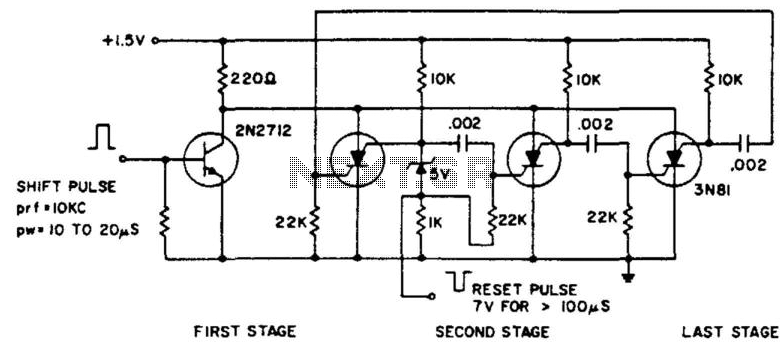
The ring counter operates from 1.0 to 6.0 V and requires only 6 mW at 1.5 V. The reset pulse activates the first stage with its trailing edge. The maximum shift pulse width increases with voltage and approaches 70...
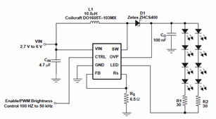
The schematic diagrams for the TPS61042 current LED driver illustrate its capability to power eight LEDs with an efficiency of 81% at 3.6V and 18.6mA. The TPS61042 is commonly utilized in applications such as white LED supply for backlight...