
Deviation Meter

The deviation monitor circuit is structured to provide accurate measurements of frequency deviation in FM signals, making it suitable for various applications in communication systems. The PLL configuration allows the device to maintain synchronization with varying input frequencies, thus eliminating the need for continuous retuning. The heterodyne oscillator's fixed design ensures stability while providing flexibility to adapt to different frequency bands through appropriate circuit adjustments.
The operational amplifiers utilized in the circuit enhance the signal processing capabilities, allowing for effective amplification of the demodulated output before rectification. The use of a micro-ammeter for visual output provides a clear indication of frequency deviation, which is essential for monitoring the performance of FM transmitters and receivers. The inclusion of a deviation sense switch further aids in diagnosing issues related to signal integrity, such as non-linearity or distortion, which may arise during transmission.
The design emphasizes the importance of component selection, particularly in the choice of diodes and resistors, to ensure optimal performance and accuracy. Gold-bonded diodes are favored for their low forward voltage drop, which minimizes errors in low-voltage applications. The resistor network is critical for biasing the diodes correctly, ensuring that the meter operates within its linear range, thus providing reliable readings across the specified deviation ranges.
Overall, this deviation monitor represents a robust solution for detecting and measuring frequency deviations in FM signals, leveraging advanced circuit techniques to achieve high levels of accuracy and reliability in various operational contexts.A deviation monitor can be made by connecting some form of frequency modulation (FM) detector to an AC voltmeter and calibrating the meter in units of frequency deviation. One method of detecting or demodulating the FM signal is to use a phase locked loop (PLL). A voltage controlled oscillator (VCO) is locked to the FM signal frequency by comparin g its output with the FM signal in a phase comparator which generates a correction voltage to control the frequency of the VCO. This voltage is a function of the signal frequency and hence is a demodulated version of the signal frequency.
Conventional FM demodulators, such as the frequency discriminator, require precise tuning, that is, they are fixed frequency devices. Tuning can only be achieved by varying the frequency of a heterodyne oscillator. The advantage of the PLL is that it can be used to detect FM signals, without retuning, over a frequency range equal to the capture range of the loop.
When heterodyning for a different frequency range, only a fixed frequency heterodyne oscillator is required. The following text describes a deviation monitor which has been constructed using a phase locked loop as an FM detector.
Circuit detail is shown in Figure 1. The essential circuit blocks are a heterodyne oscillator, frequency mixer, phase locked loop and a metering circuit calibrated in frequency deviation. The heterodyne circuit is fixed for the 2 metre band but the monitor could be used on other bands with other appropriate heterodyne circuit design.
The VCO in the phase locked loop is set for a free running frequency of 1 MHz. The approximate capture range is 500 kHz, hence the VCO will lock to any frequency in the range of 750 to 1250 kHz. Equipped with the crystal specified, a frequency of 145. 3 MHz is generated and this heterodynes with signals in the 146. 05 MHz to 146. 55 MHz region to provide a beat frequency for the PLL input within 750 to 1250 kHz. The spectrum 146. 05 to 146. 55 includes the input frequencies of popular repeaters (old channels 41 to 48) and simplex (old channels 49 to 51).
Integrated circuit N1 (type XR215) and associated circuits operate as a phase locked loop and FM detector. The free running frequency of the VCO in N1 is set by the values of C7 and R23. Demodulated FM output is amplified by an operational amplifier in N1 package and by N2 (uA741). The switched feedback network of N2 (SW1, R12, R13, R14) is also used to select the deviation range by changing the gain of N2 circuit.
Deviation ranges of 0-5 kHz, 0-10 kHz and 0-50 kHz are provided. The audio output of N2 is rectified by either diode V1 or diode V2 to charge either C10 or Cl1 to the peak value of the audio waveform. Positive or negative peak is selected by switch SW2 to feed micro-ammeter M1 via either R20 or R21. In conjunction with these resistors, M1 forms a peak reading voltmeter calibrated in terms of frequency deviation.
Deviation sense switch SW2 is provided to check for difference readings between positive and negative peaks, indicating non linearity or peak clipping on the demodulated waveform. There is always a problem with meter scale linearity when using semiconductor diodes as meter rectifiers at low voltage.
The metering circuit has been devised so that the linear scale of the micro-ammeter can be used over its essential range. Gold bonded diodes (type 0A47) were selected because of their low forward voltage and these are forward biased by resistor network R17, R18, R19, R22 and R24 to the point where conduction just commences.
A small residual reading is indicated on the meter but linearity is good above five percent of the scale. Resistors R17, R19, R22 and R24 are shown in the diagram as 1 percent but if these are not available, the important point is to select R17-R19 and R22-R24 as matched pairs.
The RF input circuit is arranged to load the transmitter to about 1W, terminated in 50 ohms. The power should not 🔗 External reference
Related Circuits
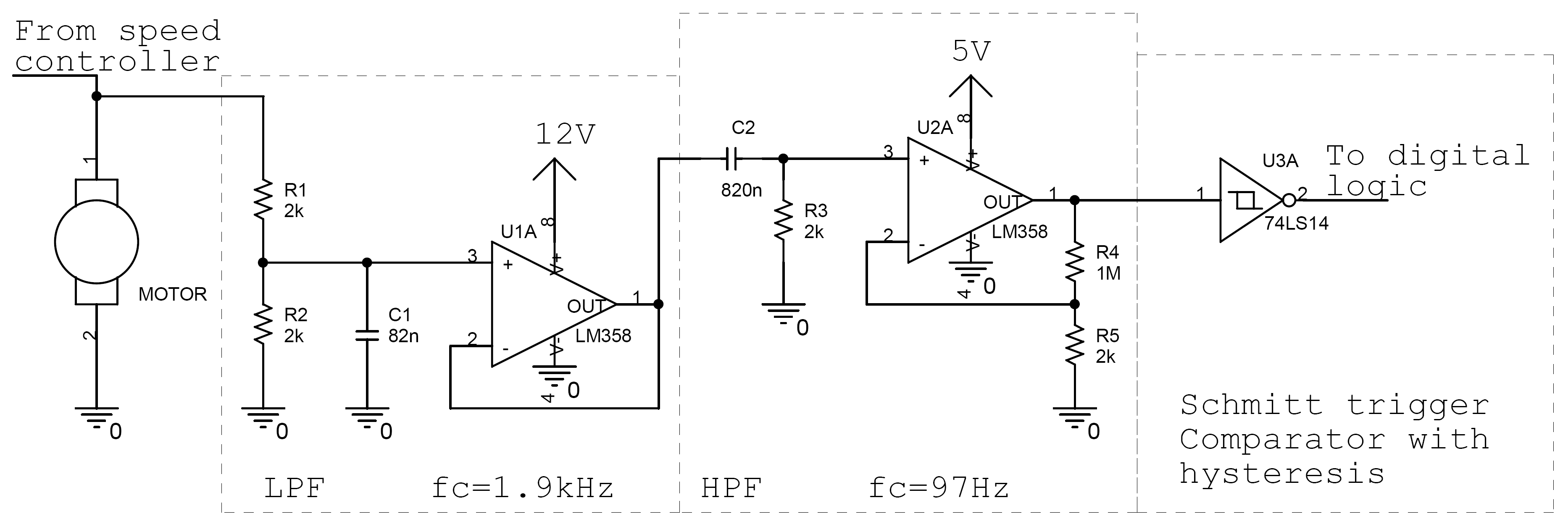
Controlling the speed of a motor is crucial in various applications, particularly in robotics. Numerous techniques exist for adjusting motor speed, each offering distinct advantages and disadvantages. This document outlines the construction of a motor controller that regulates the...
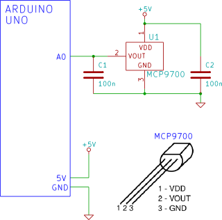
The Arduino reads temperature from an MCP9700 temperature sensor IC and displays the temperature in the Arduino IDE serial monitor window. The circuit utilizes an Arduino microcontroller along with an MCP9700 temperature sensor integrated circuit (IC) to measure ambient temperature....
This is a simple ohm meter that is small to build. The circuit operates with a constant current around T1. The current depends on the emitter through S1 can be chosen. These are the ranges of the meter. The...
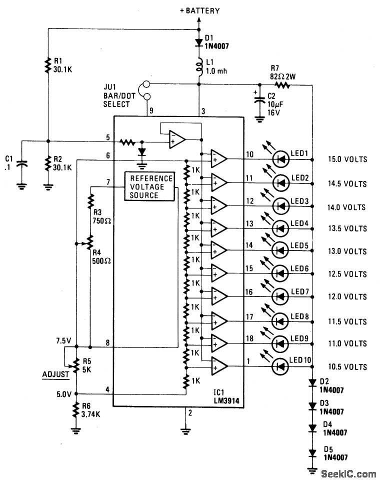
This display utilizes ten LEDs to indicate a voltage range from 10.5 to 15 volts. Each LED corresponds to a 0.5-volt increment in voltage. The main component of the circuit is the LM-3914 dot/bar display driver. A trimmer potentiometer,...
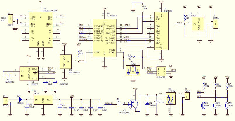
This is the fully featured, jammed packed temperature readout unit. I can measure temperature from up at 8 DS1820 digital temperature sensors all on the same 1-wire bus. That's right only 3 wires are needed to go to all...
The LM35 from National Semiconductor is a precision centigrade temperature sensor that provides an analog output voltage. It operates within a temperature range of -55°C to +150°C and has an accuracy of ±0.5°C. The output voltage corresponds to 10mV...