
DC Motor Controller and Tachometer
DC motors are constructed by wrapping coils of wire around a core, which is placed within a magnetic field created by permanent magnets or electromagnets. When voltage is applied to the windings, current flows through the coils, generating another magnetic field. This interaction can either attract or repel the two magnetic fields, causing the windings to move and rotate the motor's central shaft. After completing half a rotation, the current direction in the windings reverses due to a component known as the commutator ring, allowing the motor to continue spinning.
The primary function of the speed controller is to adjust the motor's speed. However, the term "speed controller" can be misleading, as while it enables the motor to spin faster or slower, it does not provide a means to predict the actual speed. Additionally, the motor's speed is influenced by the load it is driving. In summary, the speed controller allows for some degree of control over motor speed, but it does not provide precise speed measurements.
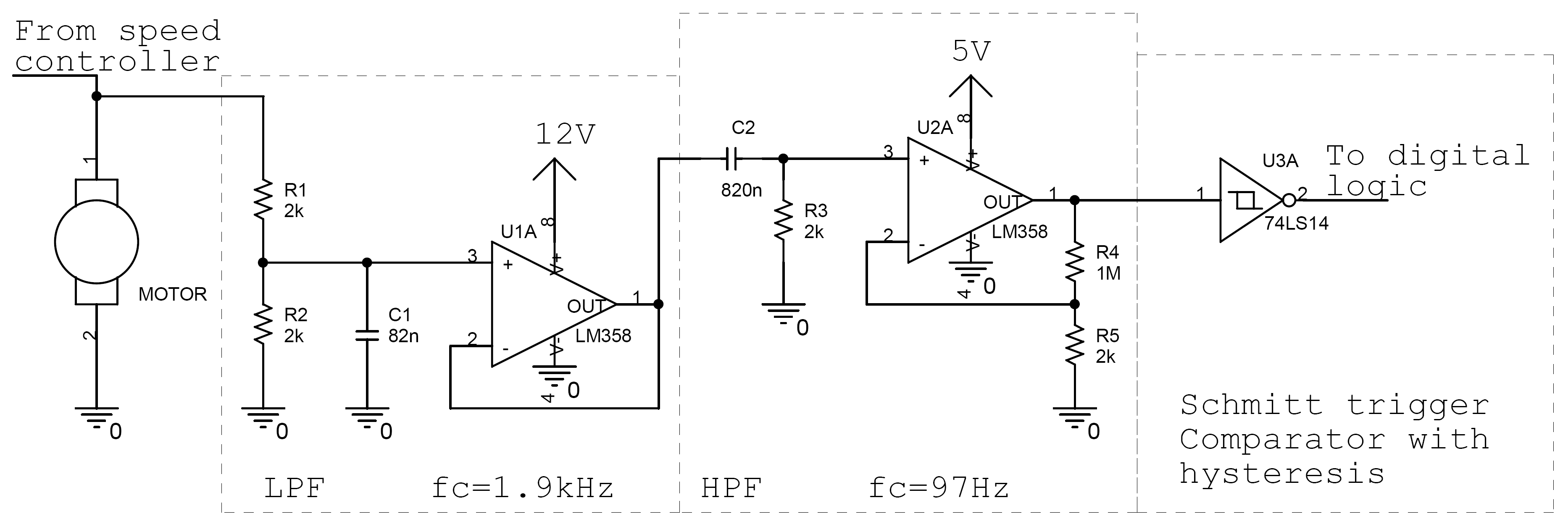
The input voltage (Vin) can be any signal voltage. For digital control, an R-2R ladder digital-to-analog converter (DAC) may be employed, while manual control can be achieved using a potentiometer configured as a voltage divider. The operational amplifier (U1A) utilized in this design is a single-supply op-amp, which operates without a negative power supply. This is particularly advantageous in battery-powered applications, such as robotics, where dual power supplies (positive and negative) are impractical. The LM358 is a suitable choice for a single-supply op-amp; alternatives such as the LM158 or LM258 can also be used, as they exhibit similar characteristics.
The op-amp is configured in a non-inverting arrangement. The LM317 (U2) serves as a voltage regulator. The op-amp alone lacks sufficient strength to drive a motor, while the voltage regulator can only provide a constant output of 1.25V. By combining the op-amp with the voltage regulator, it becomes possible to control the voltage output (thanks to the op-amp) while ensuring adequate power (provided by the voltage regulator) to drive the motor. The voltage regulator operates under the principle that Vout = Vadj + 1.25V. By adjusting Vadj (as illustrated in the schematic), Vout of the voltage regulator can be effectively modified.
D1 is a rectifier diode, specifically the 1N4002, although any suitable rectifier diode could suffice. Most rectifier diodes exhibit a forward voltage drop of approximately 1V. The diode's primary purpose is to safeguard the electronic components from the harsh conditions associated with motor operation. The motor's construction involves wound coils that behave as inductors. When the commutator switches, these coils can generate significant voltage spikes, potentially damaging electronic circuits and contaminating the power supply. Positioning the diode in the specified configuration helps mitigate these risks.
In summary, this motor controller design emphasizes the electrical control of motor speed while ensuring protection against voltage spikes, making it suitable for various robotic applications. The combination of the op-amp and voltage regulator provides a robust solution for controlling DC motor speeds effectively.Controlling the speed of a motor is very important in many situations especially in robotics. There are many techniques of controlling the speed of motors, each with their advantages and disadvantages. This document will show you how to build a motor controller which controls the speed of a motor by varying the input voltage.
Along the same lines, it is useful in many situations to know the exact speed of the motor (in rotations per second for example). By knowing the exact speed of the motor, we can then adjust the motor`s speed to exactly what we want.
Once again, there are many ways to do this, the method shown in this document is purely electrical and requires no additional sensors. From the outside, the 3 look almost identical. They all have a rotating shaft running through the centre. For our purposes, we will be designing our components for DC motors only. DC motors are commonly used in hobby situations and robotics. They are cheap and robust and easy to use. DC motor are made by wrapping coils of wire around a post. These windings are placed inside a magnetic field (created by permenant magnets or electromagnets). When a voltage is applied to the windings, a current will go through the coil, which will create another magnetic field.
The two magnetic fields may attact each other (like two opposite poles of magnets) or repell each other (like two similar poles of magnets). This will cause the the windings to move and rotate the central shaft of the motor. After making a half a rotation, the current going through the windings will go in reverse (due to a switch known as the commutator ring) and the motor will continue spinning.
Far better descriptions can be found here: The purpose of the speed controller is to vary the speed of the motor. The name "speed controller" is somewhat of a misnomer. We can tell the motor to spin faster or slower, but we cannot predict the speed of the motor. On top of that, depending on the load that the motor is driving, the motor`s speed will be effected as well.
In summary, the purpose of the speed controller is to have some control over the motors speed, but we cannot tell exactly how fast the motor is spinning. Vin can be any signal voltage. If you are controlling this motor through a digital interface, you may want to use an R-2R ladder DAC.
If you want manual control, you can use a potentiometer as a voltage divider. The op-amp (U1A) is a single supply opamp, which means that it can function without a negative power supply. In most battery powered situations (like on a robot), it is not practical to have dual power supplies (positive and negative) which most op-amps require.
The LM358 is a good single supply op-amp. If you can`t find any LM358`s, use LM158`s or LM258`s. They are similar enough that the circuit should still work the same. The op-amp is in the non-inverting configuration: The LM317 (U2) is a voltage regulator. The op-amp alone is not strong enough to drive a motor. The voltage regulator by itself is only capable of producing a constant 1. 25V. By using a voltage regulator in conjunction with the op-amp, we can control the voltage (thanks to the op-amp) while having enough power (thanks to the voltage regulator) to drive a motor. The voltage regulator works by keeping Vout = Vadj + 1. 25V. So by changing Vadj (see schematic), we are esentially changing Vout of the voltage regulator. D1 is a rectifier diode. The 1N4002 was choosen in this case, but any rectifier diode would do. Most rectifier diodes have a 1V drop across them when forward biased. The purpose of the diode is to protect the electronics from the harsh environment in which the motor is operating in.
The motor is built with wound coils which act as inductors. When the commutator switches, the coils act as inductors and create hugevoltage spikes which may damage the electronic circuits and pollute the power supply. By placing the diode in that positi 🔗 External reference
Related Circuits

The first schematic page contains the primary content of the design, while the second page features simulation support circuitry. The primary design controls the accessory relays and indicators. It also drives the control loop and adjusts the throttle control...
The following circuit illustrates a stepper motor controller based on the PIC16F84A integrated circuit. It features a transistor used for driving the motor. The stepper motor controller circuit utilizes the PIC16F84A microcontroller, which is a popular choice for controlling stepper...
Foggers used to generate fog and smoke effects operate by heating a special fogger fluid. They consist of a heating element that is maintained at the correct temperature using a thermostat. When the operator wants to generate smoke, they...
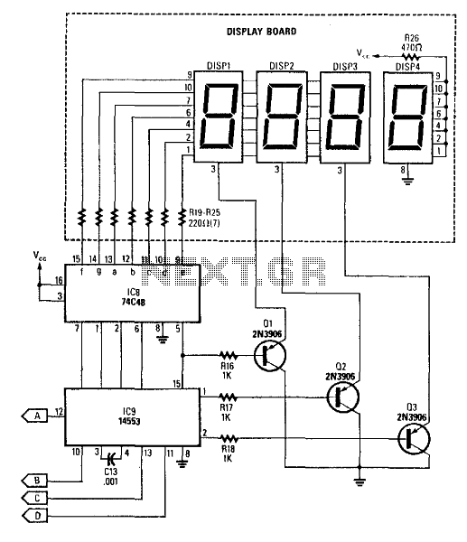
This circuit produces a readout for the digital tachometer circuit. IC9 is a 3-digit LED display driver, counter, and latch. IC8 drives the common-cathode LEDs, which are enabled by Q1, Q2, and Q3. See page 268, Fig. 46-5 for...
The AVR 8-Bit RISC microcontroller from Atmel is a widely used microcontroller. This microcontroller integrates EEPROM, RAM, an Analog to Digital converter, numerous digital input and output lines, timers, UART for RS-232 communication, and various other features. An article...
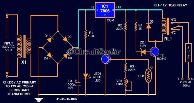
This circuit automates the control of street or porch lights. The automatic lamp controller circuit utilizes a 7806 voltage regulator IC, which can be employed to automate street lights, tube lights, or any other home electrical lighting systems. The...