
BAR GRAPH VOLTMETER
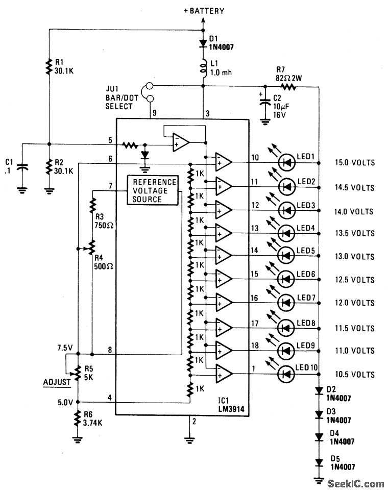
The circuit operates by utilizing the LM-3914, which is specifically designed for driving LED displays. This integrated circuit can be configured to operate in either dot or bar mode, with the selected mode determining how the LEDs are illuminated in response to the input voltage. In this application, the dot mode is employed, where each LED lights up sequentially as the input voltage increases.
The voltage divider is a critical component, where R5 is adjusted to set the reference voltage at 7.5 volts. This adjustment allows the circuit to effectively scale the input voltage range of 10.5 to 15 volts to the corresponding LED indicators. The series resistors and diodes are essential for protecting the LEDs; R7 limits the current flowing through the LEDs, ensuring they operate within safe limits, while D2 to D5 clamp the voltage to prevent over-voltage conditions that could damage the LEDs.
The inclusion of a low-pass filter, formed by L1 and C2, is crucial for maintaining the integrity of the voltage readings. This filter helps to smooth out any transient voltage spikes that may occur due to fluctuations in the power supply or other external disturbances, thereby providing a stable input to the LM-3914.
Additionally, diode D1 is a protective measure that prevents damage to the circuit in the case of reverse polarity connection. This feature is particularly important in practical applications where incorrect connections can occur, ensuring the longevity and reliability of the display circuit. Overall, this LED display circuit is a robust solution for visual voltage indication, combining effective voltage scaling, protection, and filtering to deliver accurate and reliable performance.This display uses ten LED`s to display a voltage range from 10. 5 to 15 volts. Each LED represents a 0. 5-volt step in voltage. The heart of the circuit is the LM-3914 dot/bar display driver. Trimmer potentiometer R5 is adjusted so that 7. 5 volts is applied to the top side of the divider. Resistor R7 and diodes D2 through D5 clamp the voltage applie d to the LED`s to about 3 volts. A lowpass filter made up of L1 and C2 guards against voltage spikes. Diode D1 is used to protect against reverse voltage in case the voltmeter is hooked up backward. 🔗 External reference
Related Circuits
This is an easy-to-build yet highly accurate digital voltmeter designed as a panel meter for use in DC power supplies or any application requiring precise voltage indication. The circuit utilizes the CL7107 ADC (Analog to Digital Converter) IC manufactured...

A gyrator is a circuit that utilizes active devices and transistors to emulate an inductor. In this instance, the gyrator comprises a transistor in conjunction with resistors R1, R3, and capacitor C2. Alternatively, a unity gain operational amplifier could...
In some cases, a cogwheel input is necessary for voltage measurement. By utilizing a single operational amplifier, an adapter can be created to accommodate a differential input for a ground-referenced voltmeter. It is recommended to use 1% tolerance metal...
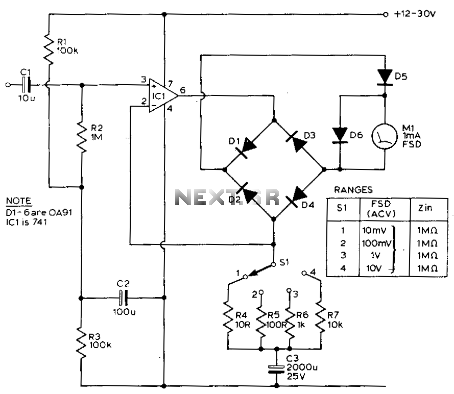
This circuit exhibits a flat frequency response from 8 Hz to 50 kHz, maintaining a -3 dB level at the 10 mV range. Furthermore, while the upper frequency limit remains consistent across less sensitive ranges, the lower frequency limit...
The voltmeter illustrated in the schematic diagram below possesses a very high input impedance. The range selector employs standard voltage divider resistors; however, due to the subsequent preamplifier utilizing JFETs, the divider can be designed with very high resistance...
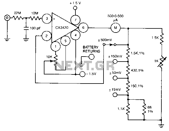
A resistance of 1,000,000 MΩ takes advantage of the high input impedance of the CA3420 BiMOS op-amp. Only two 1.5-V AA-type penlite batteries are required for use. Full-scale deflection is ±500 nV, ±150 mV, and ±15 mV. The circuit utilizes...
Warning: include(partials/cookie-banner.php): Failed to open stream: Permission denied in /var/www/html/nextgr/view-circuit.php on line 713
Warning: include(): Failed opening 'partials/cookie-banner.php' for inclusion (include_path='.:/usr/share/php') in /var/www/html/nextgr/view-circuit.php on line 713