
Device that it is self-running
Warning: Undefined array key "extension" in /var/www/html/nextgr/view-circuit.php on line 477
Deprecated: strtolower(): Passing null to parameter #1 ($string) of type string is deprecated in /var/www/html/nextgr/view-circuit.php on line 477

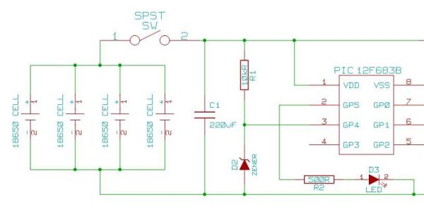
The circuit under discussion involves a 555 timer configured in astable mode, generating a continuous square wave output at a frequency of 1 kHz. This output can be used to drive various components, including transistors that amplify the signal for further applications. The LM393 comparator is utilized to compare the output voltage levels, ensuring that the waveform is correctly shaped and that the circuit operates within desired parameters.
Proper grounding is critical in this setup. The common ground connection between the function generator, the 555 timer, and any measuring instruments like oscilloscopes is essential to prevent ground loops, which can introduce unwanted noise and interference. If the oscilloscope's ground reference is not properly managed, it can create a loop that allows noise from other components or mains power to affect the circuit's performance.
The mention of the inverter battery and its grounding illustrates the importance of circuit layout and component placement in minimizing interference. The physical distance between components can significantly impact circuit behavior, as seen when moving the inverter battery affected the circuit's output.
The 100Ω resistor in series with the oscillator feed serves as a current-limiting component, protecting the BFY51 transistor from excessive current that could lead to failure. This design consideration is crucial in ensuring the longevity and reliability of the circuit.
In summary, the circuit design incorporates a 555 timer and LM393 comparator, emphasizing the importance of grounding and component placement to minimize interference and ensure stable operation. The careful selection of components, such as the inclusion of current-limiting resistors, further enhances the circuit's reliability.If the input is coming from, say, a Function Generator`s typical output clipleads, then the "black" lead or "-" or "ground" is connected to the circuit`s ground. From the Pin 3 of a 555 timer. ditto, the timer`s ground must be common with the circuit`s ground. This forms a current path. If the ground reference leads of some other, line-connected instrument like an unisolated oscilloscope
is connected elsewhere in the circuit. now you have a ground-loop that might also carry power into the circuit from the FG or even from the mains. It looks like Mr. Clean has disconnected merely the positive pole of the battery alone, from the video, and that the negative battery pole remains attached to the circuit.
Does the schematic ground indicate an Earth ground as well Is it plausible that ground currents may account for the effect Irregardless, this has to be the most exciting video of all time. From what I understand the ‰ 1kHz waveform comes from that 555 astable multivibrator and the LM393 comparator that is powered by the device itself.
See the updated diagram in my 1st post. the inverter battery (commercial inverter) was grounded and when I moved it away from the battery my circuit was attached to the effect faded with distance. At about 4:30 in the video I disconnect the input power to the circuit and the noise continues, enough to light an LED.
I think it had something to do with the old scope as well. I have a new one now. Anyway it wasn`t free energy or zipon`s. The voltage was about 13. 5 volts. When I shot the video I was still investigating it. I lit the LED with it later then discovered the battery thing after that. It was strange but that is why the clever guys like Tinsel Koala and the likes are here to help work through these things. I had to work it out for myself. But my first impression was confusion not excitement. Just because we can take a lead of the battery or capacitor does not mean there is no input. P. S. This is how things get out of hand, someone notices something strange and gets excited then a whole heap of other people who don`t understand get excited and reinforce the original persons excitement.
Then it is difficult to take the truth because of all the expectations hope and belief. Many experimenters need to learn to determine power before making claims, until then they should present their findings without the problem of everyone hyping them up. Then it can be investigated in an unbiased way. Thanks, verpies. that accounts for the similarity of the schematic with the ignition coil driver in the linked page! Identical except for the 100R in series with the oscillator feed. I hope MrClean will also show where all the instruments are connected, both "probe" and ground references.
I`ve had a similar experience myself like Farmhand describes. Disconnect a battery lead and the (whatever) keeps running. and then find that it`s being powered thru the scope ground shields looping back thru the mains ground pin to another instrument`s chassis ground and then back to the circuit somehow. Thanks, verpies. that accounts for the similarity of the schematic with the ignition coil driver in the linked page! Identical except for the 100R in series with the oscillator feed. The 100 © resistor in series with the oscillator feed is present in the lower diagram (the one with the 4 transistors 2N3055), so I monkey`d it from there because without a resistor at the base of the BFY51 transistor, it would blow up.
🔗 External reference
Related Circuits
Heavy-duty portable charger for USB devices (phones, iPad, etc.). Have you ever needed to charge your phone on the go? Unable to find a wall socket to charge your iPod?.. The heavy-duty portable charger is designed to provide a reliable...

Low Voltage Differential Signaling (LVDS) is an effective digital video signal transmission interface that supports low-cost digital audio data streaming. This article discusses the use of Maxim Integrated Products Inc.'s MAX9205/MAX9206 10-bit LVDS serializer/deserializer (SerDes) to transmit up to...
A PoE Plus power level of 30 W can be achieved by utilizing an external MOSFET along with a controller that is compatible with the older standard. Power over Ethernet (PoE) technology enables the delivery of electrical power along with...
This project originated from a desire to experiment with traditional methods of radio construction that were popular approximately 70 years ago. The aim was to explore the performance that could be achieved using simple circuits that incorporate valves or...
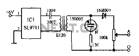
The electronic frostbite treatment instrument ASIC SL9711 consists of an oscillation circuit, a power amplifier, and a controller. It generates a sine wave at frequencies of 100 Hz and 3 Hz, followed by a step-up transformer with potentiometer adjustment...

The amplifier utilizes a single MRF245 transistor and delivers 80 W of output power with a gain of 9.4 dB across the frequency range of 143 to 156 MHz. The circuit design for the amplifier featuring the MRF245 transistor is...