
Electronic circuit diagram of frostbite treatment device
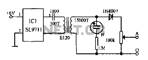
The ASIC SL9711 is designed specifically for the treatment of frostbite through controlled electrical stimulation. The oscillation circuit generates precise sine waveforms at specified frequencies, which are crucial for eliciting the desired physiological response. The 100 Hz and 3 Hz frequencies are selected based on their effectiveness in stimulating peripheral nerves and promoting muscle activity, which can be beneficial in treating conditions related to frostbite.
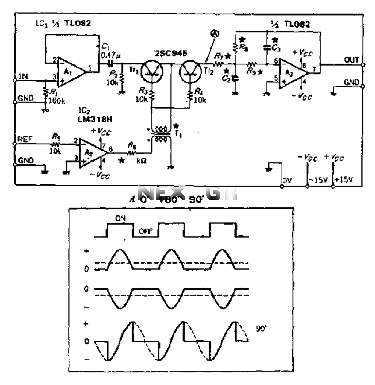
The power amplifier is integral to the circuit, as it boosts the low-level signals generated by the oscillation circuit to a level suitable for therapeutic application. The inclusion of a step-up transformer allows for the adjustment of the output voltage, which can be fine-tuned using a potentiometer. This capability ensures that the current delivered to the body can be customized for individual treatment needs, optimizing the therapeutic effects while maintaining safety.
The output stage of the device incorporates a diode that shapes the current into a pulsating waveform. This waveform is essential for stimulating nerve fibers effectively. The pulsating nature of the current induces a series of muscle contractions, which can lead to increased blood flow and pain relief. The initial muscle tremors experienced by the patient are a direct result of motor nerve activation, and as these tremors diminish, the analgesic effect begins to take place.
The mechanism behind the analgesic effect involves the suppression of sensory and motor nerve activity, which elevates the pain threshold. This is further enhanced by the inhibition of AC ripple currents, which can contribute to discomfort. Additionally, the denaturation of nerve proteins leads to biochemical changes that facilitate the release of vasoactive peptides, promoting vasodilation and improving local circulation.
Upon cessation of the pulsating current, the enhanced blood flow can aid in the recovery of frostbitten tissues, thereby supporting the healing process. The design of the ASIC SL9711 exemplifies a sophisticated approach to therapeutic electrical stimulation, combining precise engineering with a deep understanding of human physiology to address the complex challenges associated with frostbite treatment.Electronic frostbite treatment instrument ASIC SL9711 constitute an oscillation circuit, a power amplifier and controller, and generates 100Hz 3Hz sine wave, after the step-up transformer potentiometer adjustment EA loop current. Since the output of the diode added, and thus the current flowing through the body of pulsating current waveform. In the human body, motor nerve stimulation causes muscle tremor sense. After several seconds, Ma trembling feeling disappeared, sensory and motor nerves begin to be suppressed, and the pain threshold rose rendering analgesic effect due to inhibition of AC ripple current and the current through the nerve protein denaturation decomposition occurs trace, open into vasoactive peptide substance, which after a pulsating current is stopped, there improve local blood circulation and post analgesic effect.
Related Circuits

The circuit is constructed using the ICM7217 integrated circuit from Intersil, which features a CMOS up/down counter with a four-digit display. The clock generator circuit, IC3, produces a square wave clock signal with a period of one second, available...
A ringer interface circuit is designed to buffer the output of a central telephone system, which connects to multiple ringers distributed throughout a building. This circuit addresses an issue where the line overloads when ringing, requiring a reset. The...
This circuit is designed to achieve exceptional popularity, as evidenced by its record-breaking views and comments on the referenced website. As of May 3, 2013, it has garnered 760,191 views and 412 comments, with 116 views recorded on that...
Characterized by a steady flow of power when the power supply voltage fluctuates or the load changes, this circuit maintains a constant load current. The output current of the circuit is illustrated in Figure 4A. When the load varies...
Analog switches alternately pass and block the input signal through a low-pass filter to create a pulsating flow smoothing effect, converting it into a direct current (DC) signal. The operational amplifier, referred to as OP Xiao Ai, functions as...
Charging the battery in a slow manner (using a low charging current over an extended period) is the most economical and safest method. The design of the trickle charger should focus on two key points: firstly, the use of...