
Diac Applications
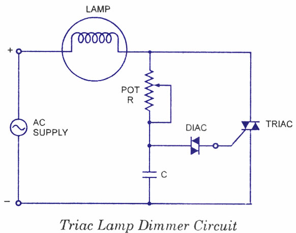
The use of diacs in triac control circuits capitalizes on their unique ability to switch on and off at precise voltage levels, making them ideal for applications requiring fine control over power delivery. In a typical lamp dimmer circuit, the diac is connected to a capacitor and a resistor network, which together create a phase delay. As the AC voltage rises, the capacitor charges until it reaches the diac's breakover voltage. At this point, the diac conducts, triggering the triac and allowing current to flow to the load (in this case, a lamp). The conduction angle is directly proportional to the charge time of the capacitor, which can be adjusted using the potentiometer.
In heater control circuits, the configuration is similar, but with additional components such as inductors (chokes) to manage the current flow and reduce voltage spikes during switching. The choke helps to smooth out the current, preventing sudden changes that could damage the triac or the load. The resistor across the diac ensures that it remains responsive to changes in the potentiometer setting, allowing for a more consistent output regardless of the position of the control knob.
Overall, the integration of diacs in triac circuits enhances their performance, providing a reliable solution for applications that require variable power control, such as lighting and heating systems. The design considerations, including component selection and layout, are crucial for achieving optimal performance and ensuring the longevity of the circuit.The diacs, because of their symmetrical bidirectional switching characteristics, are widely used as triggering devices in triac phase control circuits em ployed for lamp dimmer, heat control, universal motor speed control etc. Although a triac may be fired into the conducting state by a simple resistive triggering circuit, but triggering devices
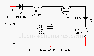
are typically placed in series with the gates of SCRs and triacs as they give reliable and fast triggering. Diac is the most popular triggering device for the triac. This is illustrated in the following applications. The circuit for a triac controlled by an R-C phase-shift network and a diac is given in figure. This circuit is an example of a simple lamp dimmer. The triac conduction angle is adjusted by adjusting the potentiometer R. The longer the triac conducts, the brighter the lamp will be. The diac acts like an open-circuit until the voltage across the capacitor exceeds its breakover or switching voltage (and the triac`s required gate trigger voltage).
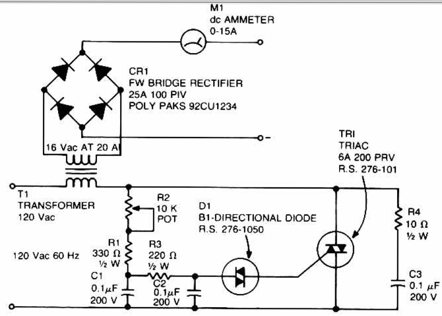
A typical diac-triac circuit used for smooth control of ac power to a heater is shown in figure. The capacitor C1 in series with choke L across the triac slows-up the voltage rise across the device during off-state. The resistor R4 across the diac ensures smooth control at all positions of potentiometer R2. The triac conduction angle is adjusted by adjusting the potentiometer R2. The longer the triac conducts, the larger the output will be from the heater. Thus a smooth control of the heat output from the heater is obtained. 🔗 External reference
Related Circuits
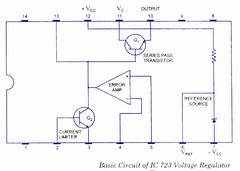
The working and block diagram of the IC 723 Voltage Regulator is provided along with the circuit diagram and applications. The IC 723 is a voltage regulator integrated circuit that is widely used for providing a stable output voltage. It...
Power demand in portable designs can require, in specific applications, more than 1 A. A method involves paralleling two DC to DC converters on the same load instead of using a single higher current converter with a lower switching...
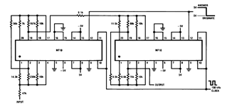
Later, there will be applications including a Basic Circuit Description, Block Diagram of the MF10, Programmable Dual Clock Generator, Butterworth Lowpass Filter, MF10 as an Input Filter and Sample/Hold, Generating Quadrature Sine Waves, and the Non-Inverting Integrator used in...
This concept involves generating a flashing light from an LED using alternating current (AC). The circuit is a simple method for flashing one or more LEDs from high voltage direct current (DC) obtained from mains electricity. It can serve...
This circuit can be used to charge accumulator and cell batteries. It features a very stable output that extends the battery life and maximizes the added battery capacity. The charging process is also quite fast, optimizing the time required...
This article presents a high reliability 1200V High Voltage Integrated Circuit (1200V HVIC) for half bridge driver applications, aimed at reducing the IC's supply current by approximately 50%. The 1200V High Voltage Integrated Circuit (HVIC) is designed specifically for half-bridge...