
MF10 Full Duplex Modem Filter Diagram Schematic and Applications
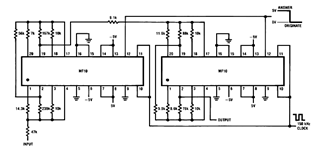
The MF10 is a versatile integrated circuit that functions in various applications, particularly in signal processing and conditioning. The basic circuit description of the MF10 outlines its operational capabilities, including its dual-input and dual-output configuration, which allows for complex signal manipulation.
The block diagram of the MF10 illustrates the internal architecture, highlighting key components such as operational amplifiers, comparators, and signal routing paths. This visual representation aids in understanding how the circuit processes input signals to produce desired output characteristics.
The Programmable Dual Clock Generator feature of the MF10 enables precise timing control for synchronous operations. This functionality is crucial in applications requiring coordinated timing, such as digital signal processing and communication systems.
The Butterworth Lowpass Filter design implemented in the MF10 provides a smooth frequency response with minimal ripple, making it ideal for applications that demand high fidelity in signal transmission. The filter's characteristics can be adjusted through external components to meet specific frequency requirements.
As an Input Filter and Sample/Hold circuit, the MF10 is capable of capturing and holding sampled values of analog signals, ensuring that digital systems receive stable and accurate data for further processing. This function is particularly important in data acquisition systems where signal integrity is paramount.
Generating Quadrature Sine Waves is another application of the MF10, which is essential in various modulation schemes and signal generation tasks. The circuit can produce two sine waves that are 90 degrees out of phase, facilitating the creation of complex waveforms.
The Non-Inverting Integrator used in the MF10 allows for the integration of input signals without inverting their phase, providing a straightforward means of signal manipulation in analog applications. This configuration is particularly useful in applications such as analog computing and waveform shaping.
Overall, the MF10's diverse applications and functionalities make it a crucial component in modern electronic systems, providing engineers with the tools necessary for effective signal processing and manipulation.You will find later some applications such as Basic Circuit Description, Block Diagram of the MF10, Programmable Dual Clock Generator, Butterworth Lowpass filter, MF10 as an Input Filter and Sample/Hold, Generating Quadrature Sine Waves, and the Non-Inverting Integrator Used in the MF10 🔗 External reference
Related Circuits

The schematic illustrates the design of a circuit that measures the resistance of the skin and transforms it into a functional switching signal. This circuit typically employs a resistive sensor, often referred to as a skin resistance sensor or galvanic...
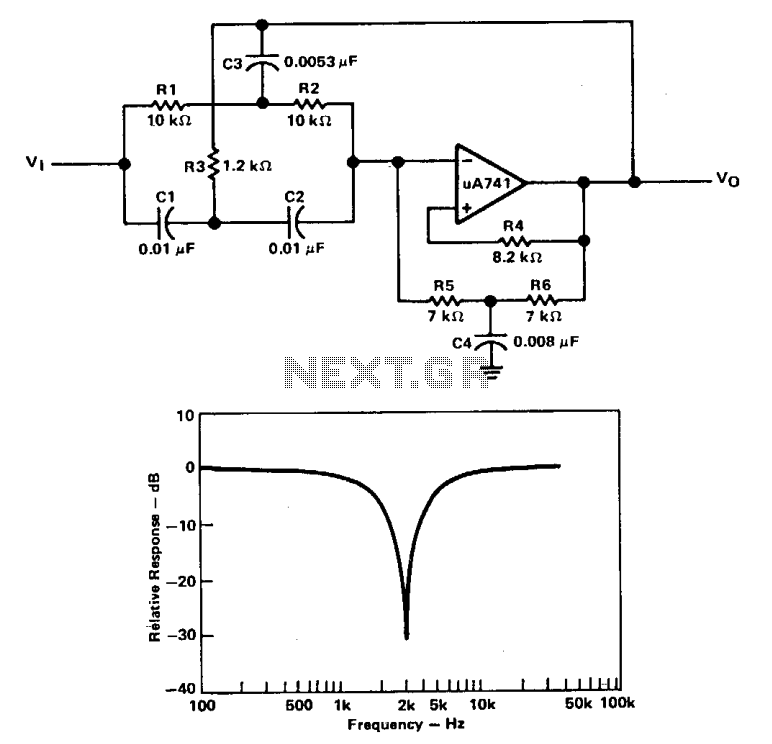
A filter with a band-reject characteristic is commonly known as a notch filter. A typical circuit employing a µ741 operational amplifier is shown in a unity-gain configuration for this type of active filter. The filter response curve illustrated represents...
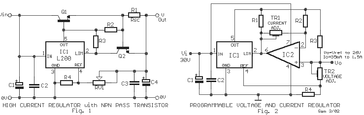
There are two regulator circuits that utilize the L200 integrated circuit from SGS-Thomson to regulate voltage and current. In circuit Fig. 1, the output voltage can be adjusted using the variable resistor RV1. In Fig. 2, both output voltage...
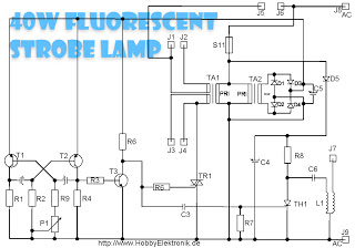
This circuit is designed for a 40 Watt fluorescent lamp. It operates similarly to a traditional strobe light, but utilizes a fluorescent tube instead. The fluorescent tube remains continuously energized, with both electrodes supplied with electricity. This current causes...

The circuit features a 24V system with a 0.5W resistor functioning as a heating element (R7), which is embedded in a sand substrate within an aquarium. The heating element is connected to 24V bulbs at both ends. The resistor...
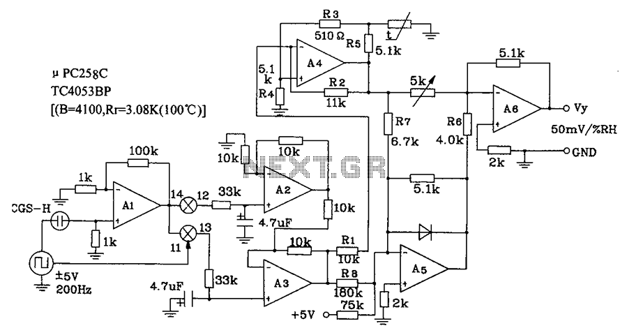
CGS-H ceramic humidity sensor constructed low humidity detection circuit diagram. The CGS-H ceramic humidity sensor is designed to detect low humidity levels within a specified range. This sensor operates on the principle of changes in capacitance that occur with variations...