
DIAL ALARM-1

The dialing alarm circuit utilizes an 8-pin microcontroller, which serves as the core processing unit for managing the alarm system's operations. The circuit's architecture is designed to be cost-effective while providing essential functionalities for security applications.
At the heart of the circuit is the BC557 PNP transistor, which acts as a switch. When a trigger pulse is applied to the base of the BC557, it conducts and supplies power to the microcontroller. This initial activation is crucial as it allows the microcontroller to begin executing its programmed instructions. The microcontroller's GPIO pin GP2 is configured to output a high signal, which maintains the power to the "turn-on" circuit, ensuring that the alarm system remains active during its operation.
An opto-coupler is integrated into the circuit to provide electrical isolation between the low-voltage microcontroller and the high-voltage telephone line. When the microcontroller activates the opto-coupler's LED, it triggers a corresponding phototransistor, which in turn engages a high-gain Darlington transistor. This configuration is essential for ensuring that the telephone line is "picked up," allowing the dialing process to commence.
Once the line is established, the microcontroller is programmed to dial two pre-defined phone numbers. This functionality is critical for alerting the called party in the event of an intrusion. The program may also include various alerts or messages that can be communicated through the phone line, providing the recipient with information regarding the nature of the alarm.
The design accommodates multiple sensors that can be connected in parallel to the single input line. This flexibility allows for various detection mechanisms, such as motion sensors or door/window contacts, to be integrated into the system. The overall circuit design emphasizes efficiency and reliability, making it suitable for a wide range of security applications while maintaining a low cost.This is the lowest cost dialing alarm on the market and shows what can be done with an 8-pin microcontroller. The complete circuit is shown below. You cannot see all the features of this project by looking at the circuit - most of them are contained in the program.
So, read on and see what we have included. Dial Alarm-1 has a single input (although a number of sensors can be placed in parallel on the same input line). The circuit requires a trigger pulse to turn on a BC 557 transistor. This delivers power to the microcontroller. The micro starts to execute the program and outputs a high on GP2 to keep the "turn-on" circuit active.
It also turns on the LED in the opto-coupler and this causes the line to be "picked up" via a high-gain Darlington transistor. The micro then dials two phone numbers and executes a series of events to alert the called party of an intrusion.
🔗 External reference
Related Circuits

A repertory dialer phone contains a library of phone numbers that can be entered and dialed, allowing access to up to fifteen frequently used numbers. It also includes the capability to store the last dialed number or an additional...
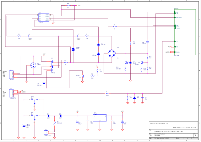
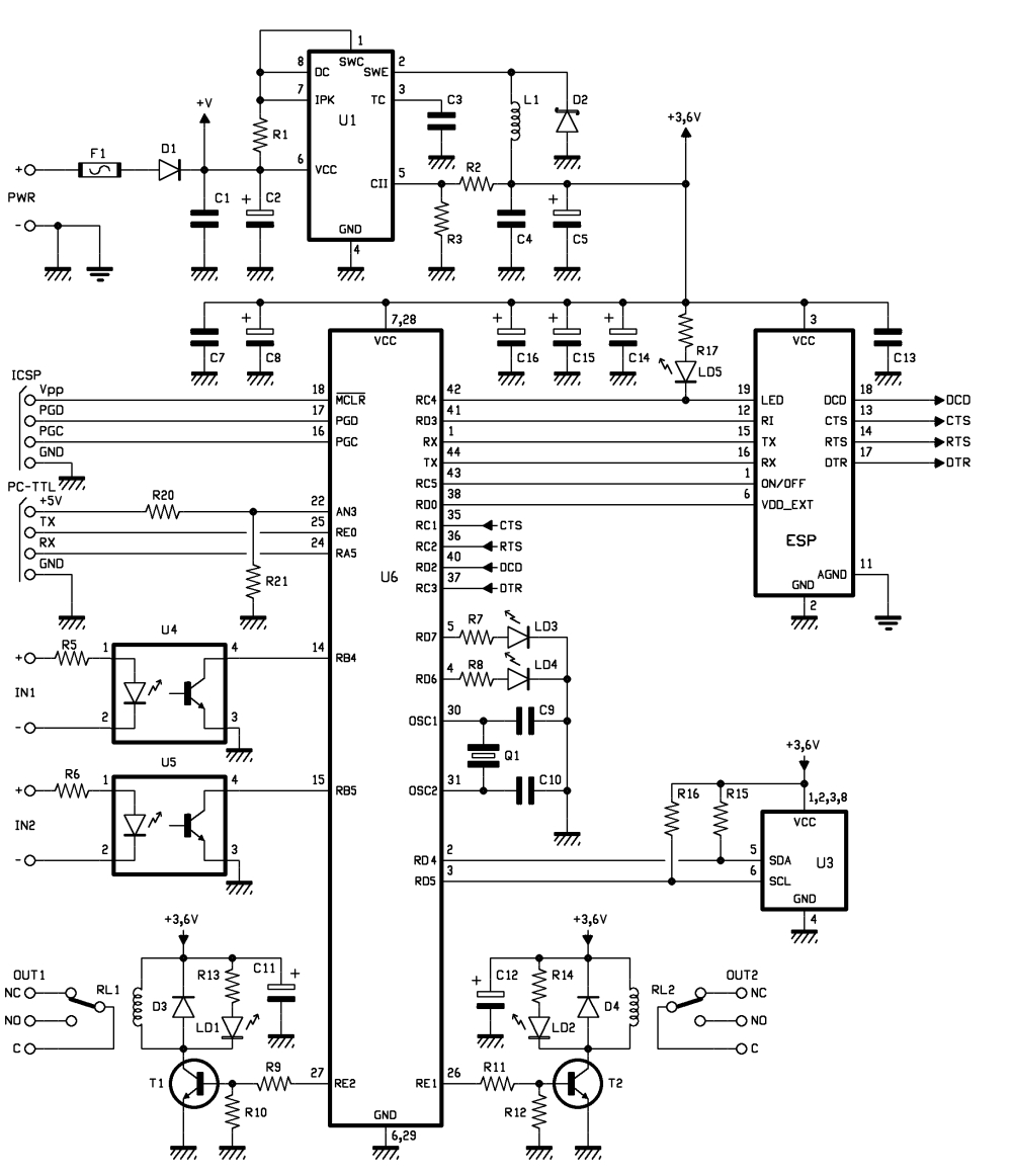
SINCLAIR is a one-channel phone dialer capable of transmitting alarm messages, which have been previously recorded to non-volatile DAST memory, over the commuted phone line to designated numbers stored in non-volatile EEPROM memory. The SINCLAIR phone dialer operates by utilizing...
Connected to a burglar alarm or fire alarm, this device facilitates phone calls that play voice messages. It is controlled via DTMF actuators, allowing for immediate operation. In recent years, several telecontrols based on the SIM900 GSM module have...
The circuit uses a NTE1690 DTMF dialer chip and a PIC16F690 microcontroller. Because this is an IP phone and I cannot just send the DTMF tones over the line, the easiest place to plug in the box is between...
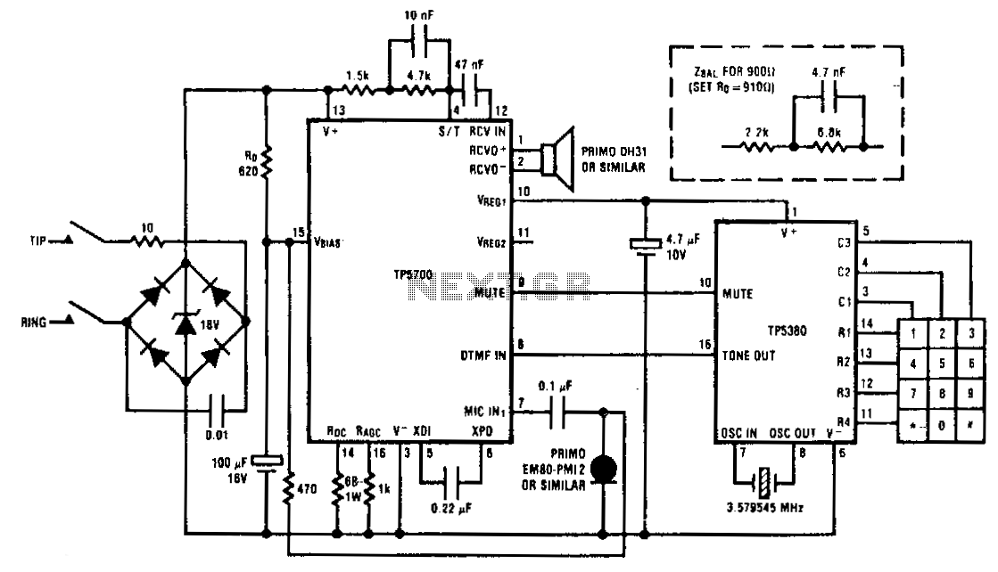
This circuit illustrates the TP5700 interfacing directly with a low-voltage DTMF generator. VREGt provides the required minimum bias of 2 V to enable the TP5380 to detect key closures and pull its mute output high. Subsequently, VREGt switches to...
The XR-T5990 single-chip pulse/tone dialer is a silicon gate CMOS circuit that performs both pulse and tone dialing functions. It is designed to operate directly from the telephone line or from a separate small power supply. Additionally, a 17-digit...