
GSM Voice Dialer with Automation Control
The described system integrates various electronic components to create an effective remote alarm solution. The SIM900 GSM module serves as the core communication interface, enabling both voice and text message alerts, which are essential for immediate emergency notifications. The microcontroller, specifically the PIC18F46K20-I/PT, orchestrates the entire operation, ensuring that the system responds accurately to input signals and executes the necessary commands for alarms and notifications.
The power management circuit is designed to accommodate a wide voltage range, ensuring adaptability to various power sources while maintaining stable operation through the use of capacitors and a protection diode. The incorporation of opto-isolators enhances safety by electrically isolating the control circuitry from high-voltage inputs, which is crucial in alarm systems where reliability is paramount.
The device's ability to distinguish DTMF tones directly via the SIM900 module simplifies the design by eliminating the need for an additional DTMF decoder, thus reducing component count and potential points of failure. The user-defined control over which phone numbers can access the system adds an essential layer of security, ensuring that only authorized personnel can manage the alarm system.
Overall, this electronic schematic represents a sophisticated integration of communication, control, and safety features, making it a versatile solution for remote monitoring and emergency response in both residential and commercial settings.Connected to a burglar alarm or fire alarm in the event of making phone calls playing voice messages. Controlled via DTMF actuators can operate on the spot. In recent years we have introduced several telecontrols based on the SIM900 GSM module. We released schematics and code for a gate opener (that activates when receiveing a call from a given nu
mber), a GSM thermostat to manage the temperature of remote houses with simple text messages, a remote alarm control with DTMF and, last but not least, a remote alarm with I/O and controlled via calls or SMS. Many of these tools send text messages or place phone calls in response to changes to the electrical inputs.
In some cases, especially when the receiver is a human, nothing is like a voice that clearly yields you screaming fire in progress! , or thieves in the house! etc. That`s why and also since we love things that speak (see our Voice shield for Arduino ) we decided to design a remote alarm, with text to speech capabilities and able to send DTMF commands (which allows quick and easy remote configuration).
This device can be controlled by the phone keyboard and only accept calls from a defined group of numbers (8) that must be stored in the device or from any number, as long as a password is provided. Controls are there for management for output relays, inputs, as well as for some operational settings.
The most attentive of you will have noticed that the schematic is missing a component, ie: the DTMF decoder where`s the mystery Well, we can do without 8870 (the decoder that always equipped our telecontrols in the past) because since few months SIM900 module can directly handle DTMF decoding. This means that all new SIM900 are able to inform the microcontroller and clearly distinguishing a DTMF two-tone from another.
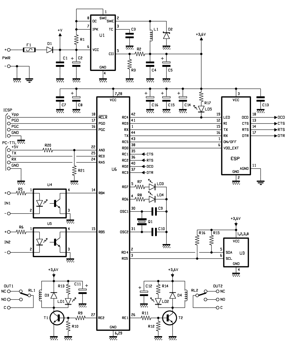
Well, let`s start with the analysis by the main component, ie the microcontroller that manages the GSM / GPRS module, checks the logical conditions of the two opto-isolated inputs and controls the two relays. Power supply is not stabilized DC voltage (applied to points named +PWR and -PWR) its value is between 9 and 32 V; it is filtered downstream the D1 protection diode from polarity inversion by means of the C1 and C2 capacitors.
F1 fuse allows to protect the circuit and the power source in the event of a short circuit in the integrated controller that follows. The microcontroller, the speech synthesis modules and GSM modules, as well as the rest of the circuit, are made to operate at 3.
6 V, derived from a switching (U1) based on MC34063 integrated and used as series PWM regulator with inductance winding. The UART inside the PIC18F46K20-I/PT, is accessible from pins 44 (transmission) to 1 (reception) and is used to give commands to the mobile phone and the voice module, sharing the same bus; the GSM module is cyclically interrogated using the TX in order to verify SMS arrival, while TX and RX together serve, during calls or messaging, to communicate between the microcontroller and the GSM module.
With regadrs to the voice module, TX imparts commands and RX reads incoming data. The CTS (Clear To Send), RTS (Request To Send) and DCD (Data Carrier Detect) are actually not used as such, but they instead form the four-wire SPI bus the microcontroller uses to communicate with the speech module. The voice module is mounted on the base board and, upon it, it takes place the phone circuitry. Now let`s see the alarm inputs read by the RB4 and RB5 I/O, both configured as input and provided with internal pull-up resistor; each reads the state of the output transistor of the corresponding optocoupler.
Each input (IN1 and IN2) is active when subjected to a voltage value between 3 and 30 V. The collector of each optocoupler is connected to a pin of the microcontroller (14/U4 and 15/U5). Once a 3 volts voltage is applied to IN1, the photocoupler lites up the LED and the phototransistor output is into conduction 🔗 External reference
Related Circuits
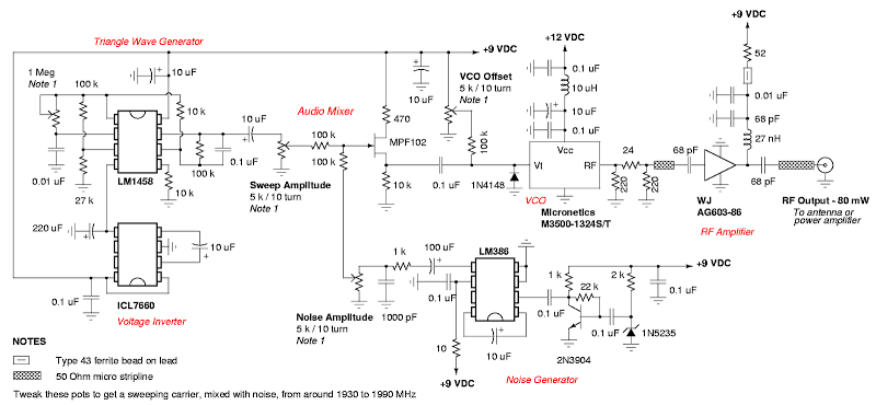
A DIY GSM jammer schematic diagram designed for use exclusively with GSM1900, operating within the frequency range of 1930 MHz to 1990 MHz. The GSM1900 cellular network is utilized in the USA, Canada, and most countries in South America....
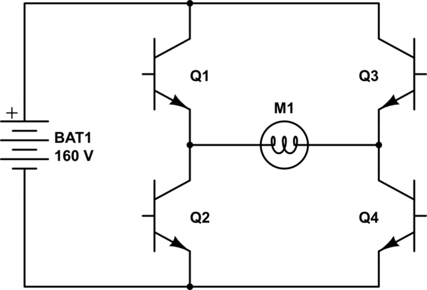
The project involves controlling a single-phase AC induction motor using two IGBTs. One IGBT is designated for switching the PWM signal to the motor, with a fixed PWM frequency of 16 kHz, while the second IGBT is employed for...
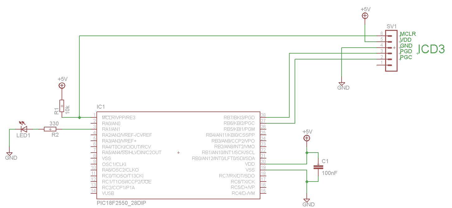
The LED blinks as expected, then pauses for an indefinite duration, flashes again a different number of times, and turns off again, displaying no discernible cyclic behavior. It activates without any external input, indicating that there is likely no...
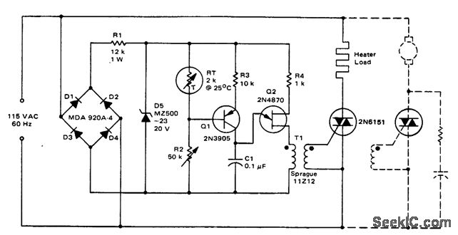
Triac temperature-sensitive heater control. This circuit can be modified to control a motor with a constant load. While the circuit is designed for heating applications, it can also be adapted for cooling by interchanging RT and R2 (courtesy of...
A schematic diagram for the remote analyzer is presented. The circuit operates from a basic 5-V power supply, which includes components PL1, S1, T1, a bridge rectifier made up of diodes D1 through D4, capacitor C1, and a common...

A simple oscillator circuit that varies the duty cycle over a wide range without affecting the frequency. It is a variation of the simple 555 astable oscillator. The use of an air-variable capacitor for frequency control is innovative. When...
Warning: include(partials/cookie-banner.php): Failed to open stream: Permission denied in /var/www/html/nextgr/view-circuit.php on line 713
Warning: include(): Failed opening 'partials/cookie-banner.php' for inclusion (include_path='.:/usr/share/php') in /var/www/html/nextgr/view-circuit.php on line 713