
Digital 5V Power Supply using L296

The L296 Power Switching Regulator circuit is designed to efficiently convert input voltage to a stable output voltage while minimizing thermal output. The circuit typically consists of several key components: the L296 IC, a Schottky rectifier (BYW80), an inductor, a capacitor, and additional filtering components as required.
The L296 IC is the heart of the circuit, functioning as a switching regulator that rapidly turns the input voltage on and off, effectively controlling the output voltage. The Schottky rectifier is crucial for its fast switching characteristics, which help in reducing power losses during the rectification process. The inductor stores energy when the switch is closed and releases it when the switch opens, smoothing out the output current. The capacitor further filters the output, ensuring a steady DC voltage with minimal ripple.
To enhance performance, especially in sensitive applications, additional filtering stages can be implemented. This may involve using LC filters or RC filters to attenuate any high-frequency noise that may remain after the initial filtering. Shielding techniques can also be employed to protect against electromagnetic interference (EMI).
The output current limitation feature allows for safe operation of the circuit under varying load conditions. By connecting a resistor from Pin 4 to ground, the current output can be adjusted to meet specific application requirements. The feedback mechanism via Pin 10 enables precise voltage regulation; by using a voltage divider, the output voltage can be fine-tuned to desired levels.
Overall, the L296 circuit exemplifies an efficient and compact solution for power regulation, suitable for a wide range of electronic applications where reliability and performance are paramount. For comprehensive design guidance, it is advisable to consult the manufacturer's datasheet and application notes, which provide detailed specifications and additional circuit configurations.This circuit is derived from an application note of L296, It is a Power Switching Regulator from ST. The advantage of using a switching regulator is that there is not much Heat Dissipation in this circuit. If you had to build the same with a series regulator, it would be very big due to external transistor and a huge heat sink.
This circuit takes a small place on PCB, efficiency is high so power is saved and reliability of product improves, lastly the thermal gradients within the cabinet is avoided so that any form of drift or component specs variation can be avoided. The Schottky rectifier BYW80 is used as it switches very fast 200V-20A-35nS. The Inductor and Capacitor is for the filter to get a ripple free DC from the Chopped DC output. There may be a small high frequency ripple riding on the DC signal of 5V in most SMPS circuits. So for very sensitive circuits use extra filters and shields. The Current output is limited, and can be reduced further with a resistor from Pin 4 to ground. Also if the feedback to Pin 10 is thru a Voltage Divider then more voltage can be set at the output. See the datasheet and application notes for other design details and circuits. We aim to transmit more information by carrying articles. Please send us an E-mail to wanghuali@hqew. net within 15 days if we are involved in the problems of article content, copyright or other problems.
We will delete it soon. 🔗 External reference
Related Circuits
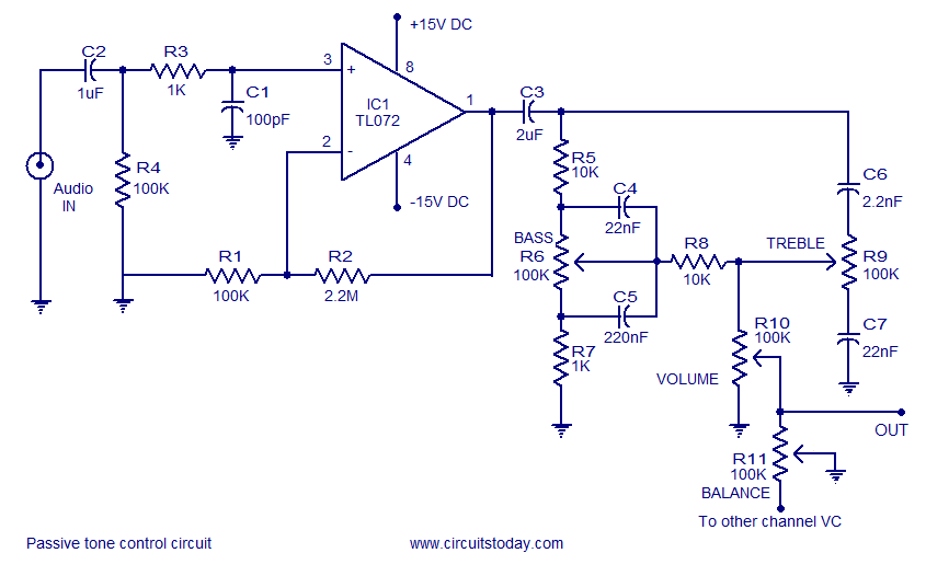
Tone control circuit utilizing an operational amplifier and a Baxandall passive tone control configuration. The overall gain is 25 dB, with a boost and cut capability of 20 dB. The circuit is powered by a dual 15V supply. The tone...
This decibel meter circuit responds to sound pressure levels ranging from approximately 60 to 70 dB (decibels). The sound is captured by an 8-ohm speaker and amplified using a transistor stage along with an LM324 operational amplifier section. A...
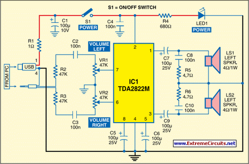
This circuit for multimedia speakers designed for PCs utilizes a single-chip architecture, operates on a low-voltage power supply, is compatible with USB power, facilitates easy heat dissipation, is cost-effective, offers high flexibility, and has a wide temperature tolerance. Central...
TIP141 is an NPN silicon power Darlington transistor designed for complementary use with TIP145, TIP146, and TIP147. It can handle up to 125 W at a case temperature of 25 °C, with a continuous collector current of 10 A...
The inexpensive flashlight utilized a small (0.22 Farad) capacitor for energy storage, which provided approximately 6.6 Joules of energy, significantly less than 1/1000th of the energy contained in a single AA alkaline cell. As a standard "super capacitor," it...
An AC mains operated single LED flasher circuit is designed using the widely used CMOS timer chip TLC555. The entire circuit is powered directly by the grid supply of 230VAC through a capacitive potential divider and associated components. This LED...