
Power 220V LED Flashing
This LED flasher circuit utilizes the TLC555 timer in an astable configuration to produce a continuous square wave output that drives a light-emitting diode (LED). The circuit is powered by the AC mains supply, which is stepped down to a safe level using a capacitive potential divider. This method is advantageous as it eliminates the need for bulky transformers, making the circuit more compact and efficient.
The capacitive potential divider consists of two capacitors in series, allowing a small amount of AC voltage to pass through while blocking the higher voltage levels. The output from this divider feeds into the power supply section of the circuit, typically involving a bridge rectifier and smoothing capacitor to convert the AC voltage into a stable DC voltage suitable for the TLC555 operation.
The TLC555 timer is configured in an astable mode, meaning it continuously switches between its high and low states, thereby turning the LED on and off at a defined frequency. The timing of the LED flashing is determined by the resistor and capacitor values connected to the timer. For instance, the frequency can be adjusted by varying the resistances and capacitance values, allowing for customization of the flashing rate according to application requirements.
In addition to the basic components, the circuit may also include a current-limiting resistor in series with the LED to prevent excessive current from damaging the LED. The output from the TLC555 can drive the LED directly, as the timer can source sufficient current for standard LEDs.
Safety considerations must be taken into account when designing this circuit, especially regarding the high voltage AC input. Proper insulation and enclosure are necessary to prevent accidental contact with live parts. Additionally, the use of components rated for the appropriate voltage and current levels is crucial to ensure reliable operation and longevity of the circuit.
Overall, this AC mains operated LED flasher circuit serves as an effective demonstration of using the TLC555 timer in practical applications, providing a simple yet functional solution for visual signaling or decorative lighting.AC mains operated single LED flasher circuit, built using the popular CMOS timer chip TLC555 is shown below. The whole circuit is powered directly by the grid supply of 230VAC through a capacitive potential divider and associated components..
🔗 External reference
Related Circuits

The camera operation failure on the Nokia 2630 has a similar solution to that of the Nokia 2600c, as both devices share the same circuit board. This issue is typically caused by hardware damage or a broken line on...
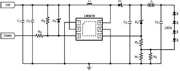
The LM3410 constant current LED driver is a monolithic integrated circuit that enables the design of high-efficiency, low-cost lighting solutions using a minimal number of electronic components. It employs current-mode control and internal compensation to ensure optimal performance across...
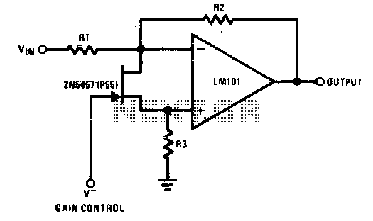
The 2N5457 functions as a voltage-variable resistor with a maximum RdS of 800 ohms. Given that the differential voltage on the LM101 is in the low millivolt range, the 2N5457 JFET exhibits linear resistance over several decades, offering excellent...
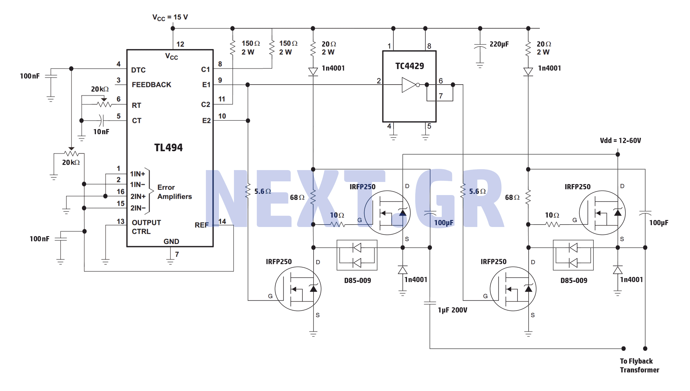
A reliable full bridge driver is essential for driving a flyback transformer. While many flyback driver schematics exist, most lack durability. The well-known Zero Voltage Switching (ZVS) driver, invented by Vladmiro Mazilli, is recognized for its reliability due to...
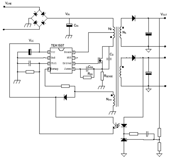
The power supply utilizing the TEA1507 driver is predominantly employed in Philips-branded televisions. This power supply achieves an efficiency rate of up to 90%, resulting in reduced cooling requirements and standby power consumption of less than 1 watt. The...
A highly practical workbench lighting unit designed for electronics hobbyists. The portable inspection lamp circuit features an onboard voltage regulator and a high-brightness 5mm white LED. It can be powered by any 9 to 18 volt DC-rated AC mains...
Warning: include(partials/cookie-banner.php): Failed to open stream: Permission denied in /var/www/html/nextgr/view-circuit.php on line 713
Warning: include(): Failed opening 'partials/cookie-banner.php' for inclusion (include_path='.:/usr/share/php') in /var/www/html/nextgr/view-circuit.php on line 713