
USB Powered Audio Power Amplifier

The multimedia speaker circuit design is a compact and efficient solution for audio amplification in PC environments. The integration of the TDA2822M IC allows for a streamlined assembly while ensuring high-quality audio output with minimal distortion. The use of USB power not only simplifies the power supply requirements but also enhances portability, making the circuit suitable for various applications, including portable sound systems.
The circuit's design incorporates essential protective elements such as the current surge limiter (R1) and buffer capacitors (C1 and C4), which help maintain stability and prevent damage to sensitive components during operation. The inclusion of volume control potentiometers (VR1 and VR2) enables user customization of audio levels, enhancing the user experience.
The Zobel network formed by resistors and capacitors (R5, C8, R6, and C10) is critical for maintaining frequency response and stability in the output stage, ensuring that the speakers operate efficiently across a range of frequencies. Proper PCB layout and the use of shielded wiring are essential to minimize interference and maintain signal integrity, particularly in environments with multiple electronic devices.
In summary, this multimedia speaker circuit represents a well-engineered solution for audio amplification, combining functionality, ease of use, and cost-effectiveness, making it an ideal choice for PC audio applications.This circuit of multimedia speakers for PCs has single-chip-based design, low-voltage power supply, compatibility with USB power, easy heat-sinking, low cost, high flexibility and wide temperature tolerance. At the heart of the circuit is IC TDA2822M. This IC is, in fact, mono-lithic type in 8-lead mini DIP package. It is intended for use as a dua l audio power amplifier in battery-powered sound players. Specifications of TDA2822M are low quiescent current, low crossover distortion, supply voltage down to 1. 8 volts and minimum output power of around 450 mW/channel with 4-ohm loudspeaker at 5V DC supply input.
An ideal power amplifier can be simply defined as a circuit that can deliver audio power into external loads without generating significant signal distortion and without consuming excessive quiescent current. This circuit is powered by 5V DC supply available from the USB port of the PC. When power switch S1 is flipped to on` position, 5V power supply is extended to the circuit and power-indicator red LED1 lights up instantly.
Resistor R1 is a current surge limiter and capacitors C1 and C4 act as buffers. Working of the circuit is simple. Audio signals from the PC audio socket/headphone socket are fed to the amplifier circuit through components R2 and C2 (left channel), and R3 and C3 (right channel). Potmeter VR1 works as the volume controller for left (L) channel and potmeter VR2 works for right (R) channel.
Pin 7 of TDA2822M receives the left-channel sound signals and pin 6 receives the right-channel signals through VR1 and VR2, respectively. Ampl i f ied signals for driving the left and right loudspeakers are available at pins 1 and 3 of IC1, respectively.
Components R5 and C8, and R6 and C10 form the traditional zobel network. Assemble the circuit on a medium-size, general-purpose PCB and enclose in a suitable cabinet. It is advisable to use a socket for IC TDA2822M. The external connections should be made using suitably screened wires for better result. 🔗 External reference
Related Circuits
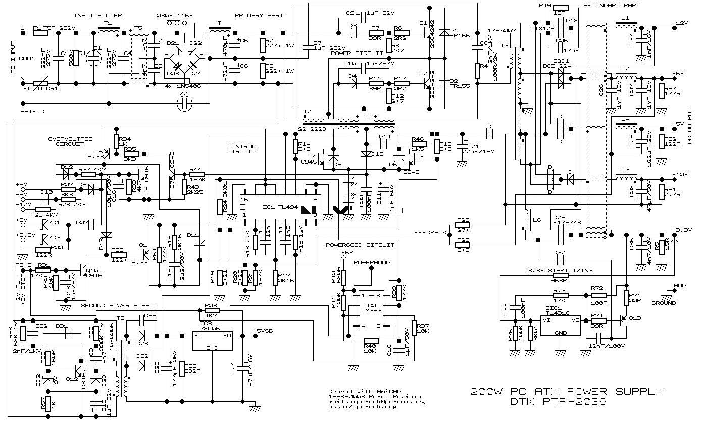
200W ATX Power Supply Circuit power supply. Visit the page for an explanation of the power supply circuit diagram. Here is a simple battery monitor circuit in which the LED continues flashing until the battery voltage is above a...
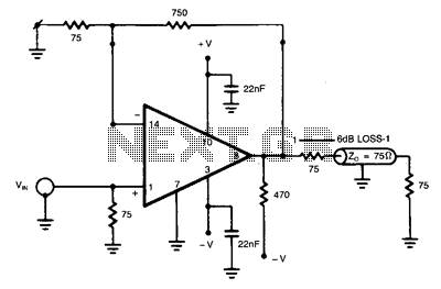
The NE5539 wideband operational amplifier can be easily configured as a color video amplifier. The gain remains stable, varying by less than 0.5% from the lowest to the highest state. The maximum differential phase shift is approximately +0.1. The...
The losses in a bridge rectifier can become significant when rectifying low voltages. The voltage drop across the bridge is approximately 1.5 V, which constitutes about 25% loss with an input voltage of 6V. This loss can be reduced...
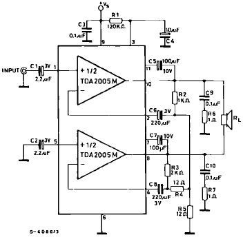
The TDA2005 is a Class B dual audio power amplifier package specifically designed for car radio applications. It facilitates the easy design of car radio power boosters. The TDA2005 power amplifier is engineered to deliver high-quality audio output in automotive...
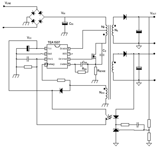
The power supply utilizing the TEA1507 driver is predominantly employed in Philips-branded televisions. This power supply achieves an efficiency rate of up to 90%, resulting in reduced cooling requirements and standby power consumption of less than 1 watt. The...
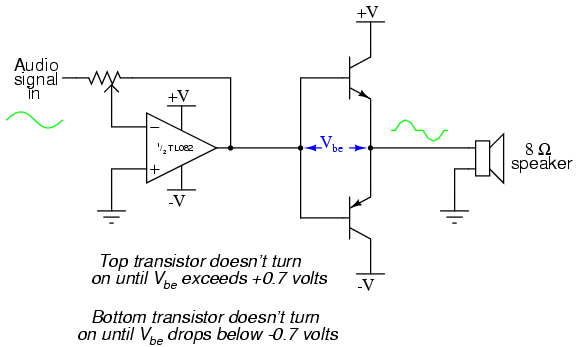
This project is an audio amplifier designed to amplify output signals from small radios, tape players, CD players, or other audio signal sources. For stereo operation, two identical amplifiers must be constructed—one for the left channel and another for...