
digital alarm clock using pic
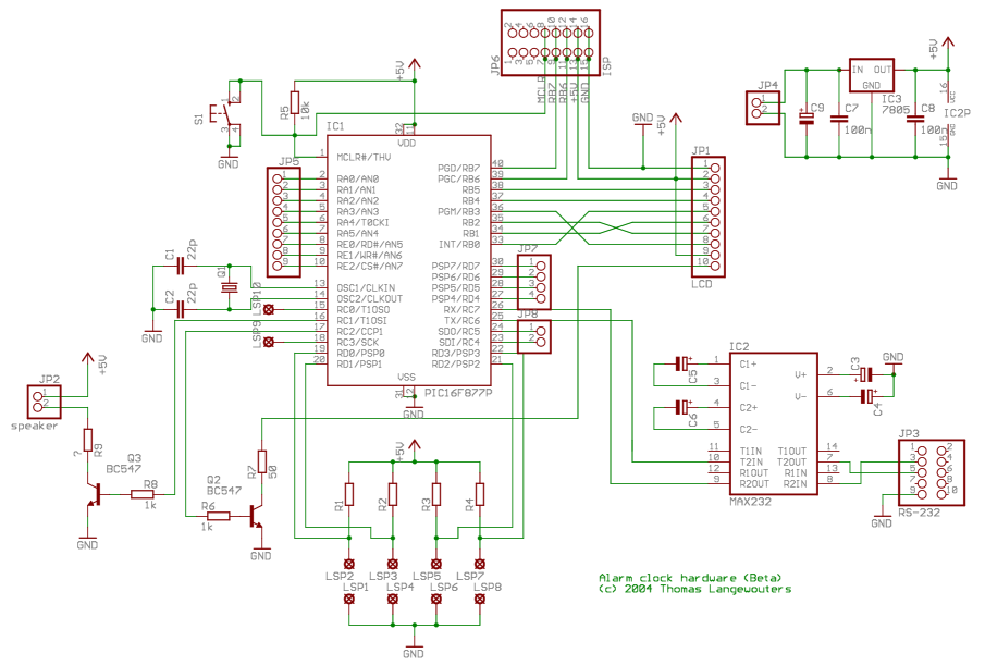
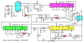
This digital clock circuit is designed for precision and user-friendliness, integrating several components to achieve its functionality. The PIC16F877 microcontroller is at the heart of the design, programmed to manage timekeeping and alarm features effectively. The Timer0 module within the microcontroller is configured to generate a 1-second delay, critical for accurate timekeeping. Roman's zero error method enhances the timing precision, ensuring that the clock remains synchronized over prolonged periods.
The display utilizes a 4G—20 character LCD with an HD44780 driver, which is capable of rendering time in a large, readable font. This choice of display not only improves visibility but also enhances user interaction. A serial port connection allows users to synchronize the clock with their computer’s time, providing an additional layer of convenience and accuracy.
Power management is efficiently handled by a 9V wall adapter, which feeds into an LM7805 voltage regulator. This component converts the higher voltage down to a stable +5V supply necessary for the microcontroller and peripheral devices. The choice of a 20 MHz external clock ensures that the microcontroller operates at optimal speed, allowing for quick processing of timekeeping functions and user inputs.
The backlight of the LCD is driven by a PWM output from the microcontroller. This feature enables users to adjust the brightness of the display according to their preferences or ambient lighting conditions, enhancing usability in various environments.
Overall, this digital clock with alarm function represents a well-integrated electronic design, combining precise timing, user-friendly display, and adjustable features, making it suitable for a wide range of applications. The availability of the complete software in JAL further supports customization and adaptation for specific user needs or enhancements.This project describes a digital clock with alarm function. It uses a PIC16F877 microcontroller to generate an accurate 1 sec delay with Timer0 using Roman`s zero error method. The time is displayed in large size font on a 4G—20 character LCD that uses HD44780 display driver. You can synchronize the time with your computer time through a serial po rt. The required power is provided through a 9 V wall adapter which is used to obtain a regulated +5 V power supply using a LM7805 IC. The microcontroller runs with a 20 MHz external clock. The backlight of LCD is driven by a PWM output from the microcontroller so that the back light intensity can be varied.
The full software written in JAL is available to download. Source Code. 🔗 External reference
Related Circuits
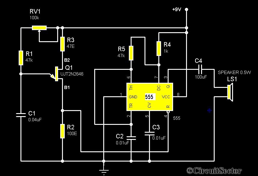
The circuit diagram illustrates a timer 555-based rain sound generator. It requires a 9V DC power supply, which can be provided by a 9V battery. The circuit utilizes a 0.5W, 8-ohm speaker to produce sound. When powered by a...

This unit is designed to interface TV sound, videotape sound, and 5.1 DVD sound to a 4 channel home theater system. It provides the following functions/options: Mix DVD center into front left/right for Phantom Center effect with optional boost...
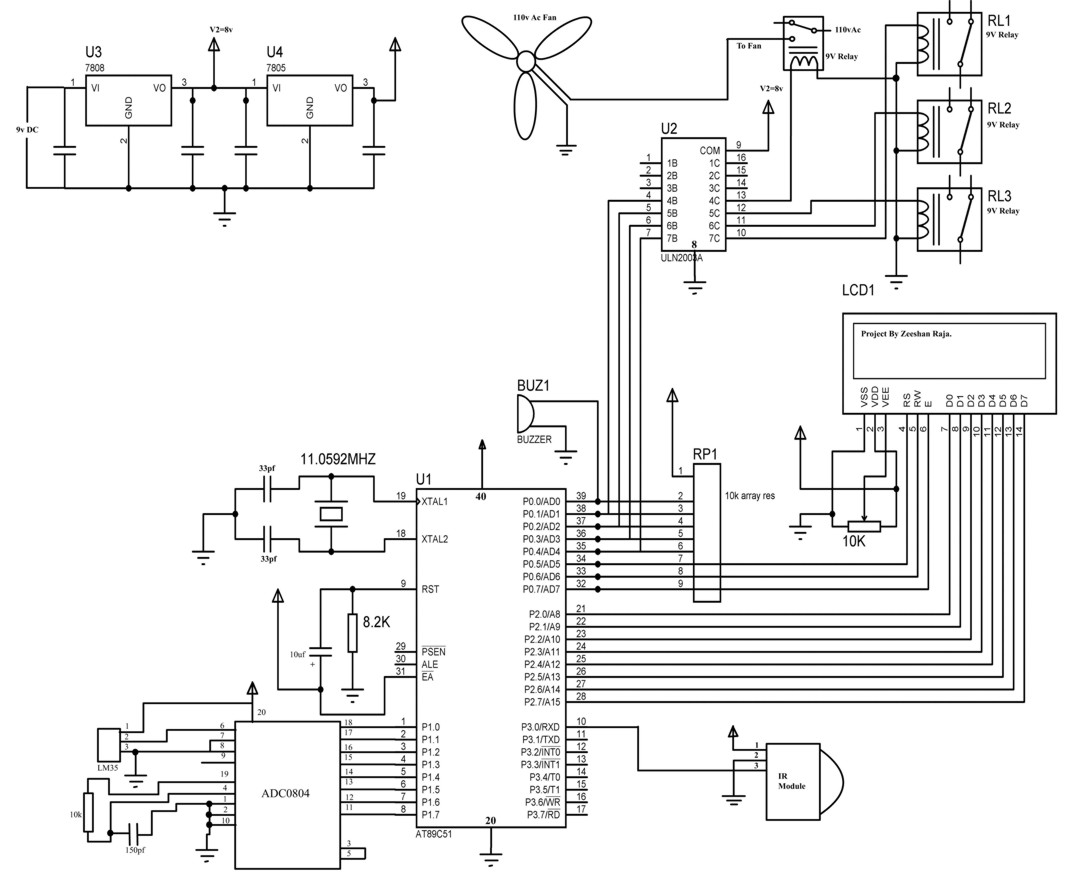
This circuit allows the use of the keys "1, 2, 3, 4" on a Philips TV IR remote to control three relays. The key "4" specifically activates the over-temperature alarm. The LM35 temperature sensor can detect temperatures from 0°C...
The CS4811 is a complete audio effects processing system integrated on a chip. This device features a proprietary 24-bit audio processing engine, substantial on-chip RAM, and a high-performance 24-bit audio codec. A serial control port enables the device to...

NOPPP is a straightforward programmer designed for the PIC16C84, PIC16F83, and PIC16F84(A) microcontrollers. It connects to the parallel port of a PC. Plans for this device were published in a magazine. The NOPPP programmer is an essential tool for developers working...
The following circuit illustrates a Cat and Dog Repellent Timer Circuit Diagram. Features include the capability to maintain a deep cycle battery charged by a solar panel. The Cat and Dog Repellent Timer Circuit is designed to provide a humane...
Warning: include(partials/cookie-banner.php): Failed to open stream: Permission denied in /var/www/html/nextgr/view-circuit.php on line 713
Warning: include(): Failed opening 'partials/cookie-banner.php' for inclusion (include_path='.:/usr/share/php') in /var/www/html/nextgr/view-circuit.php on line 713