
Circuit digital Clock Timer

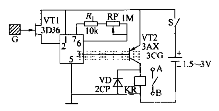
The Cat and Dog Repellent Timer Circuit is designed to provide a humane method for deterring unwanted pets from specific areas. The circuit operates by utilizing a timer mechanism that activates a repellent device at predetermined intervals. This can be particularly useful in gardens, yards, or other outdoor spaces where animals may cause disturbances.
The schematic typically includes a microcontroller or timer IC that controls the operation of the circuit. A power supply is required, which can be sourced from a deep cycle battery charged by a solar panel. This renewable energy source ensures that the circuit remains operational without the need for conventional power, making it environmentally friendly.
Key components of the circuit may include:
1. **Microcontroller/Timer IC**: This component is programmed to turn the repellent device on and off at specific intervals, ensuring that it operates only when necessary.
2. **Repellent Device**: This could be an ultrasonic emitter or a spray mechanism that releases a non-toxic repellent when activated.
3. **Power Supply**: A deep cycle battery is connected to a solar panel, allowing for continuous charging. The battery should be capable of providing sufficient voltage and current to power the circuit and the repellent device.
4. **Control Circuitry**: Additional components such as resistors, capacitors, and diodes may be included to protect the circuit and ensure stable operation.
5. **User Interface**: A simple interface may be integrated to allow users to set the timer intervals and adjust the operation of the repellent device according to their needs.
Overall, the Cat and Dog Repellent Timer Circuit provides a practical solution for managing animal presence in designated areas while promoting a sustainable approach through the use of solar energy. The design emphasizes efficiency and user-friendliness, making it suitable for various outdoor applications.The following circuit shows about Cat And Dog Repellent Timer Circuit Diagram. Features: used to maintain a deep cycle battery from a solar panel, .. 🔗 External reference
Related Circuits
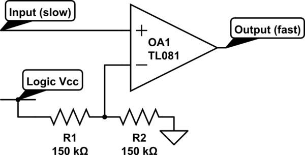
Invert a signal to drive FETs with rapid rise and fall times. It was suggested to use an inverter (not a chip) instead of logic chips, which are designed to be either fully ON or OFF. The individual has...

This is a circuit design for a PWM speed control circuit for DC motor rotation. The circuit features two functions: Forward-Reverse operation and Regenerative Braking. The control is achieved using a MOSFET. The circuit allows for the control of...
This circuit is a constant current protection type that limits the output current to a specific value in cases of over-current and short-circuit conditions. When the output current exceeds this limit, the output voltage decreases. The CW200 power management...
The Accu charger circuit is straightforward and simple to construct, requiring no more than ten components. In addition to its ease of assembly, this charger circuit is also cost-effective and highly efficient. The circuit requires a power supply from...
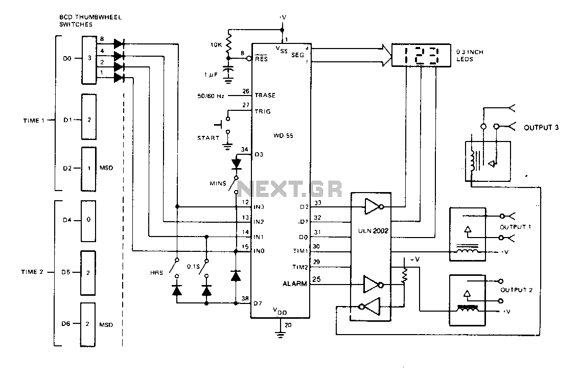
The device is a switch programmable on/off or interval timer that features three relay-switched outputs. Output one activates for the duration of time one, output two activates for the duration of time two, and output three activates for the...
This meter is unique as it does not utilize a D'Arsonval movement or digital display for frequency readings. Instead, the measured frequency is indicated on a hand-calibrated dial. Any audio signal applied to the circuit is amplified by U1,...