
Rain Sound Generator Using NE555 PCB
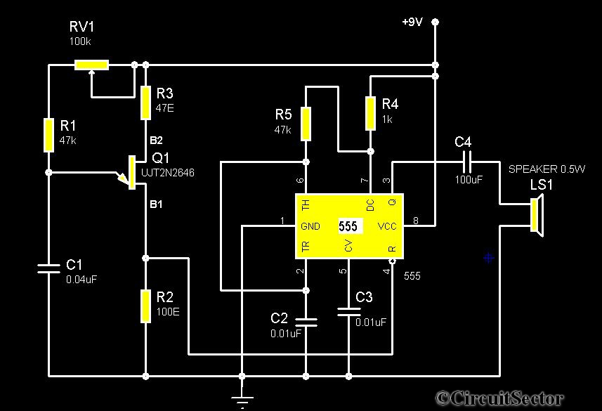
The timer 555-based rain sound generator circuit employs a combination of a UJT relaxation oscillator and a 555 timer IC to create a realistic rain sound effect. The UJT (uni-junction transistor) acts as the primary frequency generator, producing a square wave oscillation that is dependent on the selected capacitance value of capacitor C1 and the characteristics of the 2N2646 transistor. This oscillator's output is crucial as it directly influences the operation of the NE555 timer by continuously resetting it, ensuring that the timer is in a state of constant oscillation.
The NE555 timer is configured in astable mode, which allows it to produce a continuous square wave output. The frequency of this output can be adjusted by varying the resistor and capacitor values connected to the timer. The output from the NE555 is then fed into the connected speaker, which converts the electrical signals into audible sound waves. The combined effect of the UJT oscillator and the 555 timer creates a sound that mimics the gentle patter of raindrops, making the circuit ideal for sound effects in various applications.
Powering the circuit with a 9V battery provides sufficient voltage for both the UJT and the NE555 timer to function effectively, while the 0.5W, 8-ohm speaker is capable of producing the required sound output without distortion. This circuit can be further enhanced by incorporating additional components such as filters or tone control to refine the quality of the sound produced, thereby allowing for customization based on user preferences. Overall, this rain sound generator circuit serves as an excellent example of utilizing basic electronic components to achieve a specific auditory effect.The circuit diagram shows a timer 555 based rain sound generator. The circuit requires a 9V dc power supply and can be fed from a 9V battery. The loud speaker for producing sound is of 0. 5W 8ohm speaker. The circuit will readily generate a rain like sound whenever the circuit fed by a 9V supply. The rain generator has two sections one is a UJT rela xation oscillator. This oscillator is build upon the uni junction transistor 2N2646. This oscillator produces a fixed frequency as per the value of C1. This continuously resets the 555 because the UJT oscillator output is connected to the reset pin of the NE555. On the other hand, the 555 IC works itself as a astable multivibrator. This process result in the generation of a rain like sound from the speaker. 🔗 External reference
Related Circuits
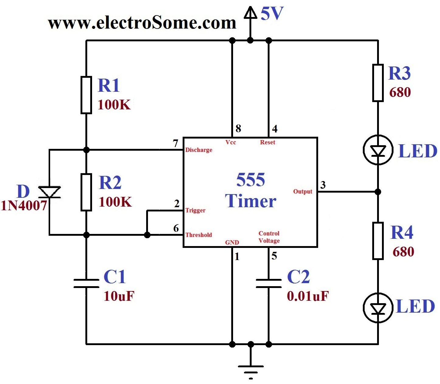
A dancing light can be easily constructed using a 555 timer wired in astable mode. This circuit alternately blinks two LEDs with a certain delay and can be modified to include additional LEDs or to control incandescent lamps. The...
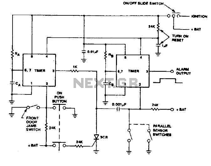
The 555 timer generates a reliable delay, enabling the driver to deactivate the alarm and eliminating the need for an external control switch that could be compromised. Additionally, the RCS prevents the activation of timer B unless it is...
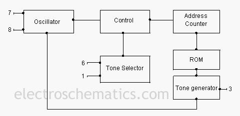
The UM3561 is a versatile ROM integrated circuit capable of generating multiple siren tones, including those that simulate police sirens, ambulance sirens, fire brigade sirens, and machine gun sounds. This low-power, 8-pin IC operates down to 2.4 volts and...
This text assumes some prior knowledge of PCB etching methods and recounts an experience with the toner transfer technique. For those unfamiliar with the method, additional research may be necessary. The process of constructing a circuit on protoboard is...

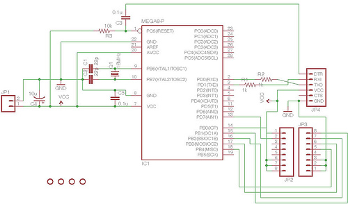
Designing a controller PCB for a 10x10 white LED matrix clock based on an ATmega328 AVR IC and a Maxim DS3234 SPI RTC. The challenge lies in controlling a custom non-standard 10x10 LED matrix. Initially, a Maxim MAX7219/7221 IC...
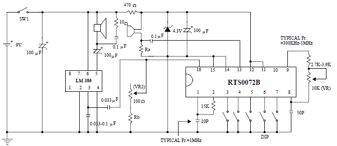
This voice changer circuit diagram is an electronic project developed using the RTS0072B single-chip CMOS LSI, specifically designed for voice-changing applications. It can transpose or distort one voice into another by encoding the input audio signals at normal speed...