
Digital Alarm Speedometer Circuit
The digital alarm speedometer circuit operates on the principle of laser reflection, utilizing a laser LED to emit a coherent light beam toward the target vehicle. The emitted light reflects off the vehicle and is captured by the laser diode, which is sensitive to the wavelength of the emitted light. The precise alignment of the laser LED and diode is crucial to ensure optimal performance and accurate readings. The circuit's design incorporates a microcontroller based on the 74AS series logic family, which provides high-speed processing capabilities essential for real-time speed measurement.
The SPST switch allows the user to turn the device on and off easily, conserving battery life when not in use. The display module, positioned conveniently for user visibility, updates the speed measurement every second, providing a clear indication of the vehicle's acceleration. If the speed exceeds 999 km/h, the system indicates this limit with the alert LED, ensuring that the user is aware of the maximum measurable speed. The device's ability to reset the display to zero after three seconds enhances its usability, allowing for continuous monitoring of multiple vehicles without manual intervention.
Overall, this digital alarm speedometer circuit is a sophisticated tool for measuring vehicle acceleration, combining advanced optical technology with efficient electronic components to deliver accurate and timely speed readings.This Digital Alarm Speedometer Circuit. It allows us to appraise the acceleration of any article moving, abnormally cars and added vehicles. The acceleration is affected in kilometers per hour (KPH). Its affectation has three digits. This alarm works with the laser reflexion. It sends laser radiation to the article and this article reflects the la ser radiation to the radar. To appraise the acceleration of a vehicle, we charge be in advanced of it. In added words, the agent charge appear in our direction. The advanced of the alarm charge point the advanced of the vehicle. The alarm has the appearance of a pistol. In this radar, it has a laser LED and a laser diode. Both accept a lens. The laser LED can accelerate a atom of ablaze to a ambit of 90 m (295 ft). It`s actual important that the ambit ambit of the laser LED is 90 m, if not, the acceleration will not be affected properly. The laser diode, which receives the ablaze arresting by the laser LED, charge be able to ascertain the ablaze which is aforementioned blush as that emitted by the laser LED.
The laser diode and the laser LED charge be placed one beside the other. They are adequate by a brave pane. They charge be placed at the advanced of the alarm and point the outside. The alarm is powered by a 9V array and it has a SPST about-face to ascendancy its ability state. The display, or the acceleration indicator, is placed at the rear of the radar, aloof on the appropriate of the afflict LED indicator. All the argumentation apparatus of the ambit charge be of the 74AS alternation and TTL type. Because they accept abbreviate time of acknowledgment (less than 1. 7 ns) and accept aerial abundance supports (more than 200 MHz). The alarm can appraise the acceleration of an article affective amid 0 to 999 km/h. Afterwards this speed, the afflict LED indicator will about-face on and the "999" will still displayed.
The alarm displays the acceleration during 3 seconds, afterwards this time, it displays "zero" (0) 🔗 External reference
Related Circuits

The primary issue with the design of a stereo amplifier that includes a total bass driver is that the signals from the left and right channels eventually become combined. This summation process minimizes the separation between channels, compromising the...

This source is selected by pressing a momentary-contact pushbutton switch (SI). Switch SI is connected to the trigger of a 555 oscillator/timer (U1) configured as a monostable multivibrator, which generates one short output pulse for each press of SI....
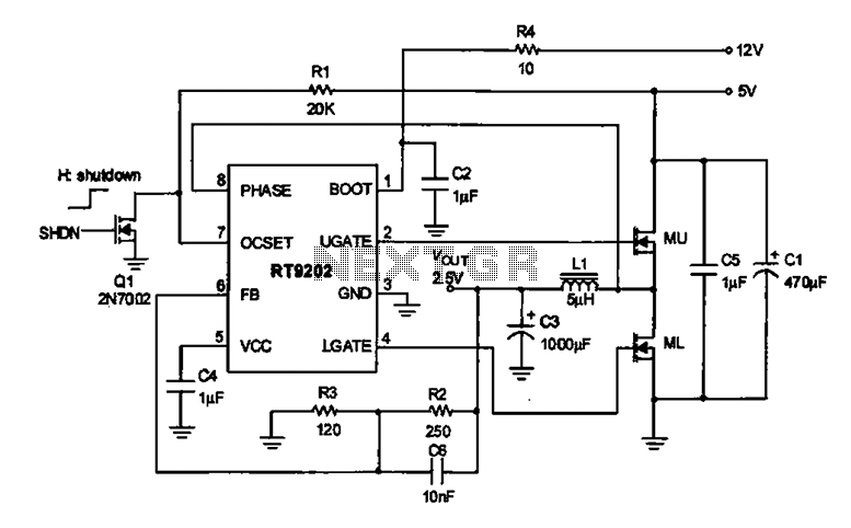
A 2.5V voltage regulator circuit is illustrated, which is part of a computer's motherboard. The circuit employs an oscillation circuit with the RT9202 control core chip, converting a 5V input supply into a regulated +2.5V output voltage, with the...
Men particularly enjoy the convenience of television remote controls, often to the annoyance of their female partners. They tend to want to know what they are missing when the TV is tuned to a specific program, leading them to...

A Siemens SLB0586A IC enables the creation of a straightforward touch-controlled dimmer circuit. This circuit regulates a triac AC switch, allowing control of loads ranging from 10 to 400 W. The Siemens SLB0586A integrated circuit is designed to facilitate the...
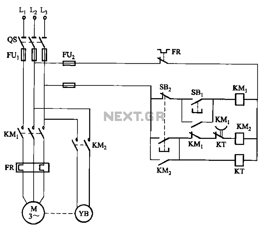
The circuit illustrated in Figure 3-123 operates as follows: When the stop button SBz is pressed, contact KMi releases, cutting off power to the motor. Simultaneously, KMz is activated, engaging the electromagnetic brake YB to hold the motor in...