
2.5V voltage regulator circuit
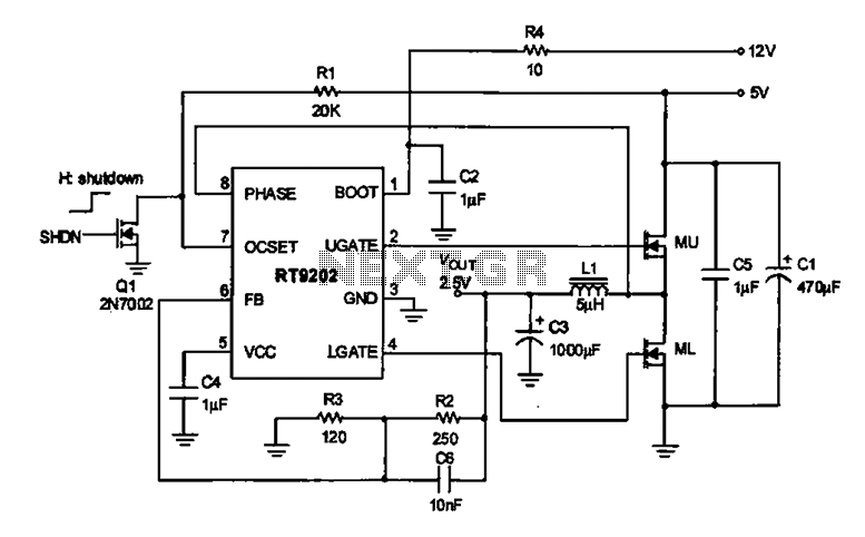
The 2.5V voltage regulator circuit is designed to maintain a stable output voltage of 2.5V from a higher input voltage, specifically 5V. The RT9202 integrated circuit (IC) plays a crucial role as the control core of this regulation process. It utilizes pulse-width modulation (PWM) to adjust the output voltage dynamically, ensuring that variations in load conditions do not affect the regulated voltage.
The circuit typically includes input and output capacitors to stabilize the voltage levels and minimize ripple. The input capacitor (C1) is placed close to the input pin of the RT9202 to filter out any high-frequency noise from the power supply. The output capacitor (C2) is similarly positioned to smooth the output voltage and enhance transient response.
Additionally, the circuit may incorporate resistors for setting the output voltage and feedback mechanisms that allow the RT9202 to monitor the output voltage continuously. This feedback loop is essential for maintaining the desired voltage level under varying load conditions. The design also considers thermal management, as the regulator may dissipate heat during operation; therefore, proper heat sinking or thermal pads might be necessary to ensure reliability.
In summary, this voltage regulator circuit is an essential component of computer motherboards, ensuring that sensitive electronic components receive a stable and reliable 2.5V supply from a 5V input, thereby enhancing the overall performance and stability of the system.2.5V voltage regulator circuit Shows the computers motherboard in 2.V voltage regulator circuit, the oscillation circuit switch IC RT9202 control core chip, will become +2.V po wer supply voltage 5v output voltage chip conscious end is + 12V power supply.
Related Circuits
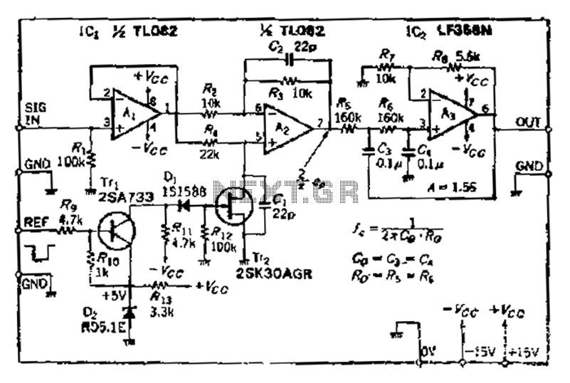
After turning off TT2, the input signal enters through chi Az, where the input resistance is very high and reaches the same potential. The inverting input terminal must also be associated with this movement. Therefore, Trr functions as a...
Thanks to the S6986, the circuit is very simple and requires few components. D2, D3, D5 and D6 forms a bridge rectifier allowing to plug the sensor connector brick in any direction. C1 filters power supply, it must be...
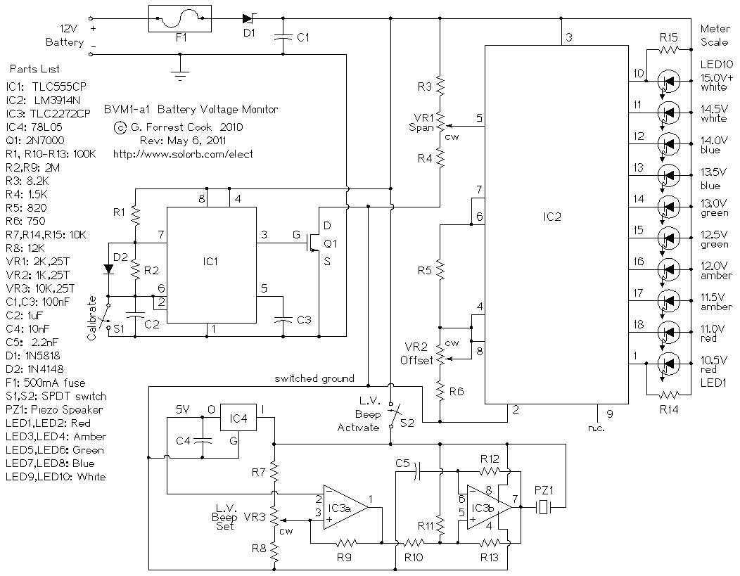
This circuit provides an audible and visual low voltage warning for 12V battery powered devices. When the battery voltage is above the set point (typically 11V), the circuit is idle. If the battery voltage should fall below the set...
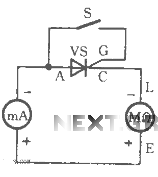
The table illustrates the capability to trigger the thyristor circuit diagram. The thyristor circuit diagram serves as a fundamental component in various electronic applications, particularly in power control and switching. A thyristor is a four-layer semiconductor device that functions as...
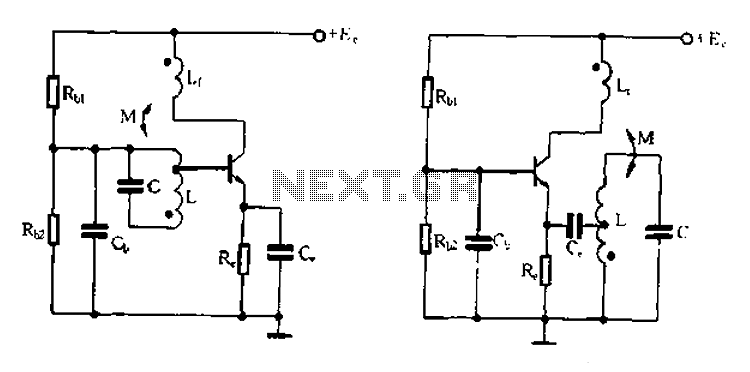
Base frequency selection, frequency-selective emitter type transformer coupled oscillator circuit The described circuit is a transformer-coupled oscillator that utilizes an emitter type configuration to achieve frequency selection. This type of oscillator is designed to generate signals at specific base frequencies,...
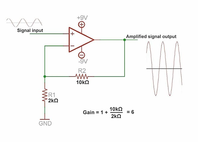
An amplifier is a device that increases the voltage in a circuit. The simplest type is an operational amplifier, and this video will demonstrate how these devices function and how to implement them in electronic applications. As an example,...