
Digital Bike Tachometer
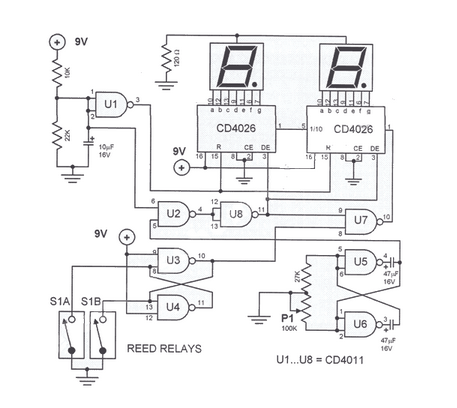
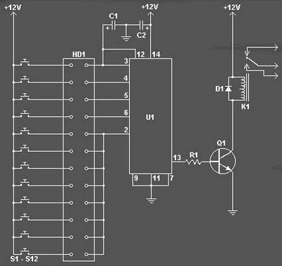
The digital DIY tachometer circuit is designed to provide accurate speed measurements for bicycles by leveraging the operation of reed switches. The two reed switches are strategically located near the wheel rim, where they can detect the passing of a magnet attached to the wheel. As the bicycle moves, the magnet passes by the reed switches, causing them to open and close in response to the magnetic field.
The output from the reed switches is fed into a microcontroller, which processes the signals to calculate the rotational speed of the wheel. The microcontroller is programmed to count the number of times the reed switches are activated within a specific time frame, allowing it to compute the speed of the bicycle in real-time.
To enhance usability, the tachometer may include an LCD display that shows the current speed, average speed, and distance traveled. Power for the circuit can be supplied by a small battery, ensuring that the system remains lightweight and portable.
Additional features may include the ability to set different wheel sizes for accurate speed calculations, as well as a reset function to clear the distance traveled. The circuit should be designed with proper filtering and debouncing techniques to ensure reliable readings, minimizing errors from false triggers caused by vibrations or noise from the environment.
Overall, this DIY tachometer provides a practical solution for cyclists seeking to monitor their speed and performance on the road.This digital DIY tachometer for bikes uses two reed switches to get the speed information of the bicycle. The reed switches are installed near the rim of.. 🔗 External reference
Related Circuits
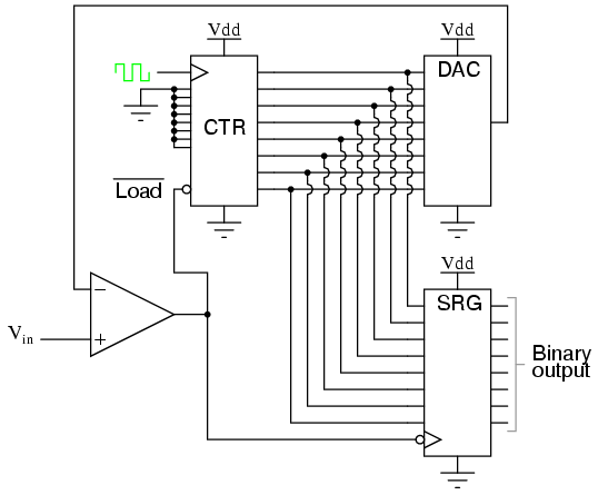
Also known as the stairstep-ramp or simply counter A/D converter, this type of converter is relatively straightforward to comprehend but unfortunately has several limitations. The stairstep-ramp or counter A/D converter operates on the principle of comparing an analog input voltage...
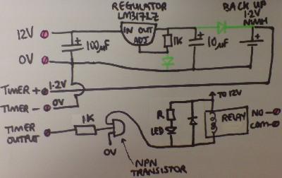
Most supermarkets today offer plug-in mains-powered digital programmable timers. These devices are designed to automatically turn lights on and off, activate washing machines while the user is away, and more. Prices start at around £5 ($10), and these products...
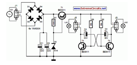
A front wheel with a built-in dynamo was purchased, providing a sine wave output of 30 Vpp at no load. Based on this, a simple power supply was designed using BD911 transistors, which are somewhat oversized for the application,...

The frequency pulses originating from the mains supply are safely insulated by capacitors C1 and C2, along with inductor L1. These pulses are amplified by transistor Q1, while diodes D1 and D2 limit any peak voltages at the input....
The basic clock circuit is similar to the binary clock and uses 7 ICs to produce the 20 digital bits for 12 hour time, plus AM and PM. A standard watch crystal oscillator (32,768) is used as the time...
The Digital Combination Lock Circuit is a schematic for a simple electronic combination lock utilizing the LS7220 integrated circuit (IC). This password-protected digital lock can activate a relay to control any device by entering a preset combination of four...
Warning: include(partials/cookie-banner.php): Failed to open stream: Permission denied in /var/www/html/nextgr/view-circuit.php on line 713
Warning: include(): Failed opening 'partials/cookie-banner.php' for inclusion (include_path='.:/usr/share/php') in /var/www/html/nextgr/view-circuit.php on line 713