
Convert Digital Mains Timer To Low Voltage
The TE7 7 Day Electronic Timer is a versatile device that can be converted for low voltage applications, making it suitable for a variety of automation tasks. The conversion process begins with disassembling the timer and identifying the necessary connections on the circuit boards. The two boards are distinct, allowing for easy separation of the mains-powered components from the low voltage circuitry. The identification of the ground and positive connections for the NiMH cell is crucial, as these will be used to control the relay.
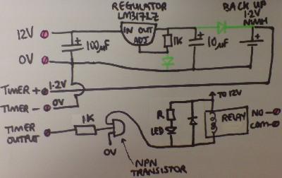
In the relay controller circuit, the selected transistor acts as a switch that is activated by the timer's output. The current-limiting resistor protects the transistor from excessive current, ensuring reliable operation. The relay, which is capable of handling higher currents, can then be used to control devices such as irrigation systems, low voltage lighting, or other appliances. This setup allows for the automation of multiple devices, providing significant convenience and energy savings.
Overall, the conversion of a mains-powered digital programmable timer into a low voltage relay controller opens up numerous possibilities for home automation and energy management, making it an attractive project for electronics enthusiasts and professionals alike.If you go to most supermarkets today you will see plug in mains powered digital programmable timers. These are designed to be used to automatically turn lights on and off, to turn washing machines on when you are out and so on. Prices start from as little as 5 pounds ($10) and these products are very feature rich often offering full seven-day programming and multiple
on-off cycles per day. Sadly these mass-produced units are only designed for mains powered devices. If you want to purchase a 12V Programmable Timer Switch you`ll find them to be feature-poor and very expensive (read linked-to article to find out more). In our article Convert Thermostat to 12V Timer Switch we showed how a £20 battery powered timer thermostat could be converted easily to operate as a programmable timer relay switch.
Unfortunately such a thermostat can be programmed with only one on-off cycle per day, and the shortest on (or off) interval it can provide is 15 minutes. In this article we will show you how a cheap supermarket bought mains timer can be converted to operate on low voltage and control (i.
e. switch on and off at programmed times) low voltage devices. The timer pictured above is a TE7 7 Day Electronic Timer marketed within Tesco`s energy saving promotion and priced at just £8. This is the timer we will convert in this article. NEW - After publishing this article, we discovered that the exact same timer is also sold by Sainsburys for around £8, but this time branded as Masterplug 7 Day Electronic Timer.
With this branding it is also sold in the UK at Halfords, Woolworths, Focus DIY, and numerous other outlets. The display on a programmable digital timer is not powered directly by mains electricity. Instead a small 1. 2V NiMH rechargeable backup cell is kept charged, and the display and electronics are powered from that.
This makes it perfect for our requirements. When we took apart the TE7, the separation of the electronic timer from the mains electricity powered components was very simple since there are two completely separate circuit boards. The two circuit boards are connected together by one ribbon cable comprising five insulated thin wires.
Following the conductive copper lines printed on the circuit board we identified the ground connection and the NiMH cell (battery) positive connection immediately. A simple voltmeter was then used to test the voltage between the ground connection and each of the other three connections with the timer set manually to ON and then to OFF.
We found that the middle connection goes high (1. 2V = NiMH backup cell voltage) when the timer is ON, and low (0V) when the timer if OFF. That is all we needed to know. Now it is possible to discard ( reuse or recycle !) the mains powered components simply by cutting through the ribbon cable as shown in the below labelled photograph: This timer requires 1. 2V to operate. Either a single AA cell can be used, or an LM317 can be set up to make a simple 1. 25V Voltage Regulator if the finished system is to be powered from a larger battery. The simplest useful circuit possible with this timer is a relay controller. The 1. 2V output which is present whenever the timer is ON can be passed through a transistor (via a current limiting resistor ) to energise the coil of a relay.
The relay can then be used to switch on and off irrigation systems, low voltage lighting, and a multitude of other devices and appliances following the settings programmed into the modified timer. While prototyping this relay circuit we used a BC238B NPN transistor and a 1K resistor simply because those were the components we had to hand, however it would almost certainly have worked with any other NPN transistor with a current rating above that of the relay coil, and a 1K resistor.
Note that if the resistor is rated too high (e. g. 10K+), or if you use a darlington transistor, there will be a time lag between the timer starting to send 🔗 External reference
Related Circuits
The successive approximation Analog to Digital Converter (ADC) is one of the most common types of ADC. It requires few components and is straightforward to operate. Additionally, it always takes the same amount of time to calculate the result....
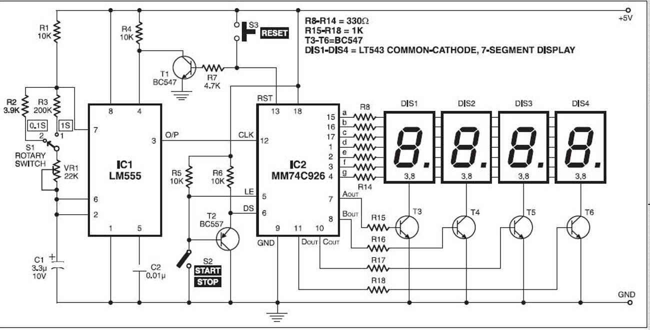
The stopwatch is constructed using a digital timer IC LM555 and an MM74C926 4-digit counter with a multiplexed 7-segment LED display. The MM74C926 features a 4-digit counter, an internal output latch, NPN output for controlling the common cathode source...
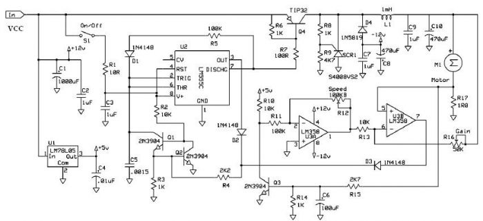
Speed regulation is achieved by monitoring the motor current with resistor R17 and utilizing it as positive feedback to offset motor resistance losses. The gain potentiometer should be adjusted to just below the threshold where motor speed begins to...
The voltage to frequency converter (V/FC - VCO) circuit consists of a UJT (uni-junction transistor) oscillator in which the timing charge capacitor C2 is utilized. The voltage to frequency converter circuit operates by converting an input voltage into an output...
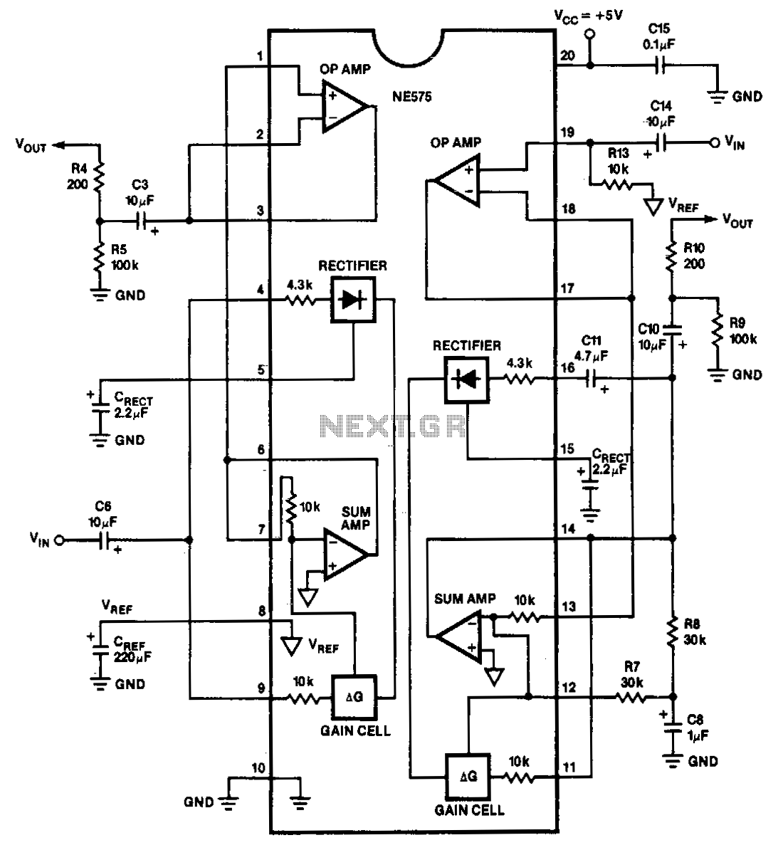
The NE575 is a dual-gain control circuit designed for low voltage applications. Channel 1 acts as an expander, while Channel 2 can be configured for expander, compressor, or automatic level controller (ALC) applications. The NE575 dual-gain control circuit is specifically...
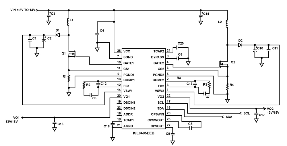
The ISL6405 is a highly integrated voltage regulator and interface integrated circuit (IC) designed to supply power and control signals from advanced satellite set-top box (STB) modules to the low noise blocks (LNBs) of two antenna ports. This device...